This thread has been locked.

If you have a related question, please click the "Ask a related question" button in the top right corner. The newly created question will be automatically linked to this question.

DLPC231S-Q1: Maximum Pin-to-Pin, PCB Interconnects Etch Lengths of DMD high speed data line

Part Number: DLPC231S-Q1
Other Parts Discussed in Thread: DLP4620SQ1EVM, DLP4621-Q1, DLPC231-Q1

Tool/software:

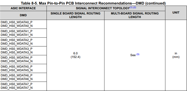
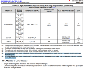
In DLPC231S-Q1 datasheet, there is a limitation of high speed data line.

The max pattern length is 152.4mm in case of single board.

Currently, in our design, those signal pattern length is little bit bigger about 10~20mm.

My question is that what I can do if display is not normal due to the pattern length.

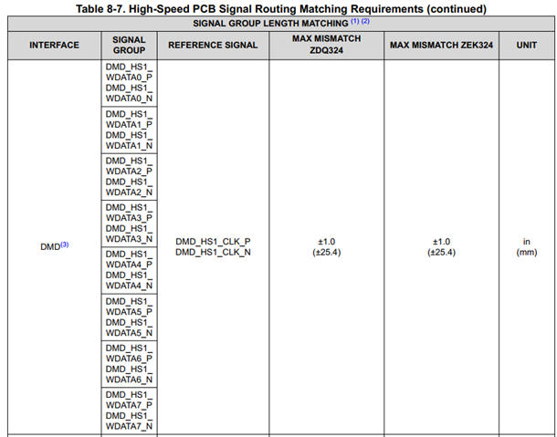
If intra patten lengths(for example clk line and data line) are adjusted almost same length, then maximum pattern length can be increased? 

  • Jin,

    Is this design already physically realized? Have you taken a look at TI's reference design that shows how we layout our DLP4620SQ1EVM? This should provide you with a good reference.

    If you have a multi-board design, I would suggest simulating as much as you can. We have seen even our 2xLVDS controllers use flex cables longer than 6 inches, so given that the DLPC231 uses subLVDS, you would likely be fine with the additional 20 mm.

    Below is a design checklist FAQ to help you out. Please reach out if there are any other questions--I'm happy to help!

    https://e2e.ti.com/support/dlp-products-group/dlp/f/dlp-products-forum/1385127/faq-dlp4620s-q1-dlp-r-automotive-design-checklists-for-schematic-and-layout

    Regards,
    Michael Ly

  • Our design is almost fixed, currently maximum length of subLVDS line is about 155mm.

    I think there are some reason you limit subLVDS line pattern length max 6 inch.

    But you said it would be fine that pattern length is longer 20mm that 6 inch. It is good news for me.

    I have one more question. As I heard TI FAE, open LDI interface(LVDS) has limitation about length between pair to pair.

    It is recommended that maximum difference on pair to pair is 5mils. It is about 0.127mm.

    But your datasheet said, clk pair and other data pair length difference limitation is 25.4mm.

    It is very big gap compare with open LDI that is also called LVDS.

    Is it really no problem if length difference between clk and data is about 20mm?

  • Hi Jin,

    Please bear with me as I explain the table you have sent me.

    The table you are showing references the connection between the DLPC231-Q1 DMD controller and the DLP4621-Q1 DMD.

    The OLDI interface is between the controller and connector for OLDI:
      

    In the first picture, we see that OLDI sends packets of data to the controller, which then processes that data through various control blocks. The processed data then gets formatted into a format the DMD understands and goes through the DMD_HS* and DMD_LS* ports. This is what the table you have shown refers to.

    To answer your question, please see below for the guideline from the DLPC23x Datasheet:

    The data above suggests a max mismatch of 0.0315±0.025 inches (or 0.8±0.635 millimeters).

    Does this answer your question?

    Regards,
    Michael Ly

  • Jin,

    I am not sure if I have sent you this yet, but we also have a design checklist for schematic and layout. If you have not taken a look at this yet, I would highly recommend it to ensure your design works the first time or to help you get an initial proof of concept.

    I recently rolled this out, and I am trying to encourage more customers to ask questions. Thanks for reaching out to us, and please continue to do so if there is something you would like extra support with.

    https://e2e.ti.com/support/dlp-products-group/dlp/f/dlp-products-forum/1385127/faq-dlp4620s-q1-dlp-r-automotive-design-checklists-for-schematic-and-layout?tisearch=e2e-sitesearch&keymatch=faq%3Atrue

    Regards,
    Michael Ly

  • No that is not answer for my question.

    My question is length matching between clk and data.

    In DLPC231S-Q1 datasheet, length difference limitation between DMD HS clk and DMD HS data is under 25.4mm.

    It is very big number compare with Open LDI requirement that say clk and data length difference is under 0.127mm.

    Open LDI is LVDS interface and DMD HS interface is sub LVDS.
    Both are similar, I think. But why is the requirement difference big?
    Do you have any simulation or test result in case of DMD HS lengh difference between clk and data is over 20mm?

  • Jin,

    Let me look into this when I get back into the office this week.

    Regards,
    Michael Ly

  • Jin,

    The reasoning why the requirement difference is big is because the DMD HS interface undergoes high speed (HS) training. This training sweeps through a range of values and determines which value is the best. The test is run continuously to ensure the controller-DMD interface works properly. This is shown in Note 2 of Table 8-7 I showed above.

    OLDI does not go through HS training, so the tolerance is much, much smaller.

    Regards,
    Michael Ly

    P.S. Back to your original question about 20 mm additional length: please ensure you are still simulating as much as you can for your design, especially if it is multi-board.