This thread has been locked.

If you have a related question, please click the "Ask a related question" button in the top right corner. The newly created question will be automatically linked to this question.

DLP4710EVM-LC: Press the SW21 switch button, the board responds, but the projector cannot be turned on

Part Number: DLP4710EVM-LC
Other Parts Discussed in Thread: DLP4710, DLPA3005

Tool/software:

Hello!
Our laboratory purchased a DLP4710EVM-LC, which could work normally at the beginning. During use, we burned data and projected it according to the user manual given by TI.
But at present, the projector is not working properly, the phenomenon is: move SW28 (PS_ON/OFF) slide switch to the ON position, led D43 (+3.3V) and D57 (INTZ) light up. When the DLP4710EVM is turned on by pressing the switch SW21, led D36 (SYS_ON-OFF), D33 (M_IRQ) and D34 (S_IRQ) no longer light up. In addition, when the switch SW21 is pressed, D56 is on - off once, and D57 is off; When switch SW21 is released, D56 is on - off once, and D57 is on.
What is the reason for this situation? How to solve it?
I look forward to your reply. I wish you a happy life and smooth work.

  • Dear Technical Support,
    Seems like similar problem here.

    Please verify for DLP4710EVM-LC and provide guidance for proper operation.
    Or confirm if can be considered as defective ?

    INV#79970586 595-DLP4710EVM-LC 1PC (Datecode 2312)

    CUSTOMER WOULD LIKE TO KNOW WHAT COULD BE THE CAUSE OF THE ERROR.
    POWER SUPPLY THEY USE IS "DC power supply (19 V DC, 4.74 A)"

    ISSUE: DLP4710 Light Control EVM does not start properly after power on.
    Specifically, the device works up to 2 in the attached image, and D43 and
    D57 light up, but then when switch (SW21) is pressed, D56 lights up for a
    second but the LEDs are not illuminated.

    Background: The device froze in the middle of operation, and when SW21 was
    pressed, the RGBLED irradiation was not completed.
    Since the device was not responding, we restarted the power supply, which
    resulted in the above symptoms.

    Per customer, they checked the below user guide.

    www.ti.com/.../dlpu079a.pdf

    Regards,
    Manuel

    (S/O#269526 / DLP4710EVM-LC operation problem)

  • I'm facing this EXACT same issue. Same symptoms and everything, out of the blue.

  • Hello Aydin, Manuel,

    Thank you for reaching out through E2E!

    I'm contacting my team and will try to get additional information on this as I have not seen this issue personally.

    Could you please advise what version of software you are running with the EVM? Also, are you still able to communicate with the module through the GUI?

    Best,

    Aaron

  • Dear Technical Support,

    The version of EVM software is 4.4.0, the version of EVM firmware is 8.1.0,  the version of  GUI software is 3.2.0.6, and I'm unable to communicate with the module through the GUI.

    Regards,
    Luo

  • Hello Luo,

    Could you please try and change the settings of 'Display' to a Test Pattern (try something like Solid Color - Cyan or something similar) and perform a 'Set'.

    If you have an error please send a snapshot of what that error is as well as a capture of the 'Debug' and 'Command Log'.

    Thank you!

    Aaron

  • Hi Aaron,

    Thanks for the verification.

    The version is 3.2.0.6. Even if GUI is used, it is not possible to communicate with the module, encountered error when try to get into the screen. The power is not supplied to EVM and it does not seem to start.

    Regards,

    Manuel

  • Hi Aaron,

    Thank you for the verification!


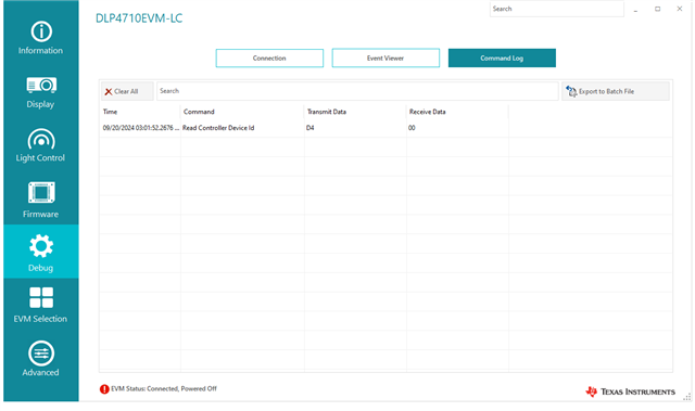
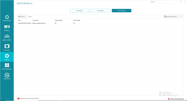
    In the first step, we move the SW28 (PS_ON/OFF) switch to the ON position, and LEDs D43 (+3.3V) and D57 (INTZ) light up, as shown in Figure 1 in the corresponding 'Command Log' screenshots.


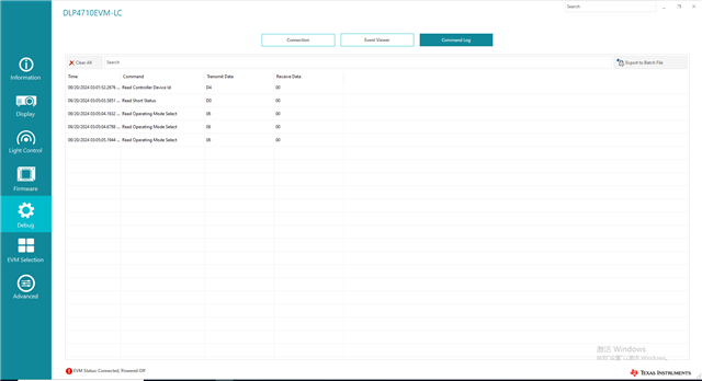
    In the second step, we press the SW21 switch, but LEDs D36 (SYS_ON-OFF), D33 (M_IRQ), and D34 (S_IRQ) do not light up. The corresponding 'Command Log' screenshots are shown in Figure 2.


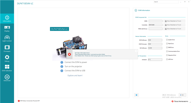
    In the third step, we click 'Information' -> 'Get'. The GUI outputs an error because the second step failed.

    Therefore, we are unable to change the settings of 'Display' to a Test Pattern (e.g., Solid Color - Cyan or something similar) and perform a 'Set'.

    Regards,

    Luo

  • Can confirm the above doesn't work either, cannot see system settings, perform a set operation.

    It seems this issue is occurring for many people, is there a fault in the product?

  • Hello All,

    Thank you for confirming the issue is widely seen.

    Because M_IRQ (D33) and S_IRQ (D34) are not toggling when the SW21 (push-button) is depressed, this indicates that the controllers are not booting properly.

    This could be caused by a few things noted below:

    1. Voltage is not correct
      1. D43 *ON* indicates 3.3V, so this is likely not the issue
    2. Flash for controller might be corrupted - Reflash both controllers utilizing the latest firmware v8.4.0 as past bug fixes have been implemented
      1. Download firmware from FW Selector website
      2. Debug section of GUI - Disconnect I2C communication and only keep SPI Flash Programming Interface connected
      3. Firmware section of GUI - Flash Firmware tab - browse to firmware file and 'Start Update'
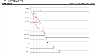
    3. The power-up sequence is not correct from the power management IC ([PMIC] DLPA3005)
      1. Probe through the lines of PMIC power-up seen in Figure 7-1 of the DLPA3005 datasheet
        1. SYSPWR (TP148)
        2. PROJ_ON (TP264)
        3. SUP_5P0V (TP182)
        4. SUP_2P5V (TP183)
        5. PWR_5P5V (TP185)
        6. DRST_5P5V (TP160)
        7. etc.
      2. If fault is seen the DLPA3005 has a hardware issue and return may be investigated

    Please advise if you are still having problems as these steps should identify the issue.

    Best,

    Aaron

  • Hi Aaron,

    Thanks for the guidance. Please refer below and advise.

    1. The power supply is correct as you said. Tried a different AC adapter, but it did not work

    2. Followed the instructions to update the firmware again, but the operation did not change

    3. Measured the voltageTP148 highTP264 lowTP182 lowTP182 low _TP183 high Compared to Figure 7-1, the behavior was quite different.

    Regards,
    Manuel

  • Hello Manuel,

    Understood, thank you for investigating these options as listed.

    Please note that you should be seeing the PROJ_ON (TP264) low until you depress SW21, and between SYSPWR and PROJ_ON should have a gap of at least 5ms.

    Everything after PROJ_ON should be automated and this is where we can start comparing the next state.

    Please advise when the sequence is broken with a scope shot of the unintended behavior.

    Thank you!

    Aaron

  • Hi Aaron,

    Please verify below/attached update.

    Measurements were taken according to the instructions and summarized on the slides.

    The following abnormalities were confirmed.

     TP182 and TP183 become high even before SW21 is pressed. (They become high only when SYSPWR is turned on.)

    TP185 does not become high even if SW21 is pressed.

    DLP4710EVM-LC_oscilloscope_.pptx


    Regards,
    Manuel

  • Hello Manuel,

    I appreciate that you provided this for us.

    I am discussing this with my team, please give me a day to discuss this internally.

    Thank you!

    Aaron

  • Hello Manuel,

    My team has confirmed that the core voltages as you've found in your PowerPoint do not gate the operation of the PMIC (DLPA3005). The power-up sequence is more accurately shown as below:

    Please note the sequence is reflected to be in this order:

    1. SYSPWR (TP148)
    2. SUP_5P0V (TP182)
    3. SUP_2P5V (TP183)
    4. PROJ_ON (TP264)
    5. PWR_5P5V (TP185)
    6. DRST_5P5V (TP160)
    7. etc.

    Please continue testing in reference to PROJ_ON to the below power sequences.

    Best,

    Aaron

  • Hello Manuel,

    I think I understand what is happening. The flash of your board might have been corrupted.

    If you would, please update the firmware through these steps:

    1. Connect your EVM through USB and power on by sliding SW28 to ON
    2. Open GUI and go to Debug and Disconnect from I2C (Command Interface)
    3. Go to Firmware -> Flash Firmware
    4. Browse to the version image file of software you've downloaded through Firmware Selector tool - or possibly a backup image file you've previously saved
    5. Start Update (this should finish in ~7 minutes)
    6. Power cycle system and reconnect I2C command interface

    Please advise if that helped at all! This should be back at the starting image for your board.

    Best,

    Aaron

  • Hi Aaron,

    Is it possible to check further ?

    Verification result as below.

          Before: when the switch (SW21) is pressed, D56 lights up momentarily but no LEDs are illuminated.

          After: Nothing happens when the switch (SW21) is pressed.

    Regards,

    Manuel

  • Hello Manuel,

    Could you share what image file have you loaded into your system during step 4?

    Best,

    Aaron

  • Hi Aaron,

    Still requesting for the image file, apology for the delay.

    Will share as soon as received.

    Regards,

    Manuel

  • Hey Manuel,

    Understood, I will continue to wait for your information.

    Additionally, I assume the others on this thread have come to resolution unless anyone responds.

    Best,

    Aaron

  • Hi Aaron, thank you for patience answering/clarifying the concern. We can close the portion I posted. Not sure but our customer had just withdrew the request. So I too will consider as completed. Could be that our customer is now able to resolve through the above updates. Thanks a lot and appreciate the guidance provided.

    Regards, Manuel

  • Hello Manuel,

    Understood, I hope this was useful in correcting the issue. It is quite common that the flash is programmed incorrectly.

    I've done it myself in a bit of confusion.

    Thank you for letting me know and I'll consider this resolved.

    Best,

    Aaron