DLPLCR4500EVM: LED enable

Part Number: DLPLCR4500EVM
Other Parts Discussed in Thread: DLPC350

Tool/software:

Dear Expert,

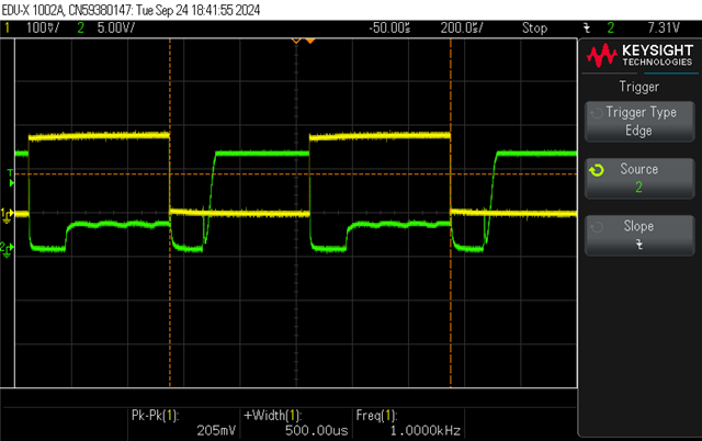
I have encountered the following issue while using the LightCrafter 4500. When measuring the emitted light with a photodiode, we observed that during the rising edge of the LED enable signal (whether driven externally by J30 or controlled by the DLPC350 via LEDX_EN), the LED intensity initially follows the enable signal but then exponentially decreases to zero, creating a dead period of approximately 200 µs before rising again. No issues were observed during the switch-off transition. This behavior presents a limitation for our application, which requires a switching time of 500 µs between two colors.

Could you assist us in resolving this issue? We are happy to provide LED intensity and enable signal traces if needed.

All the best,

Leonardo

  • Hello ,

    Thank you for reaching out and using the E2E forums! An expert from our team will review the thread and get back to you shortly.

  • Hello Leonardo,

    I assume you are using the built in LED.  The output is just an enable.  Are you saying the enable itself is going low or just the LED drive output?

    I would like to confer with the team on this one.

    Fizix

  • Dear Fizix,

    I will try to explain our tests more clearly. To check the Lightcrafter LED behavior, we performed two experiments.

    First, we programmed the Lightcrafter with a pattern sequence to alternate between a constant blue pattern and a constant red pattern every 250 µs. We used an oscilloscope to probe the variation in light intensity relative to the control signal from the board’s driver. For this, we simultaneously probed the output of a photodiode, which collected the light emitted by the Lightcrafter, and placed a probe on pin 5 of connector J29 (as indicated in the schematic, this pin is labeled “RED_LED_EN_CON”). We then started the sequence and recorded the results from the oscilloscope. In the image “Scope-0,” you can see the signal from pin 5 of connector J29 (RED_LED_EN_CON) in yellow and the light trace in green. It clearly shows that when the signal to turn on the red LED is received, the red LED initially turns on, then rapidly turns off, and begins emitting light again approximately 100 µs later.

    We were wondering why it turns off and stays off, as this is an issue for us; we set the red LED to remain on for a well-defined time in the GUI. We also connected the oscilloscope to the photodiode output alongside the digital signal from pin 7 of connector J29, labeled “BLUE_LED_EN_CON,” to check if the blue LED exhibited similar behavior to the red LED. You can see the result in the image “Scope-1.”

    Next, we programmed the Lightcrafter to display a constant red pattern and externally used the J30 connector to enable and disable the LED's ability to emit light with a square wave signal, with a period of 500 µs and a 50% duty cycle. The image “Scope-3” shows the light intensity variation of the red LED in green and the signal we sent to the device in yellow.

    This measurement shows a similar LED behavior to the one described above.

    All the best,
    Leonardo

  • Hi Leonardo,

    Thanks for  the scope shots. We will need some time to analyze this, and Fizix will be looking into it.

    Thank you,
    Michael Ly

  • Hello Leonardo,

    What photodiode are you using and how do you have it connected to the scope?

    I am also trying to figure out (except for the last image) why the photodiode seems to be showing light when the enable is low.

    I am going to send a friend invite.  This may be easier with a call.

    Fizix

  • Hello Leonardo,

    For completeness I am including the basics of this system for the E2E community.

    This system was designed in 2010 and released in 2012.  It is an older design.

    Newer systems are designed to work differently and do not switch the regulator off and on as this older design does.  The result is that the regulator takes time to come up which is what you are seeing.

    Current designs specifically shunt the current when the LED enables are off so that the regulator does not power down.  This does draw a bit more power, but does not have the dalay

    This design cannot be fixed on the controller board.  Moreover, there is no plan to change the EVM design for the 4500.

    The only real option is to use the LED on board driver disable and connect the on board LEDs to an external driver and feed the LED enables to the external driver.

    I realize this is disappointing

    Fizix