This thread has been locked.

If you have a related question, please click the "Ask a related question" button in the top right corner. The newly created question will be automatically linked to this question.

DLPC900: The DLP670S DMD only displays half of the pattern

Part Number: DLPC900
Other Parts Discussed in Thread: DLP670S,

Tool/software:

DLPC900REF-SW-5.3.0

DLPR900PROM-6.3.0

Hello,

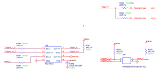
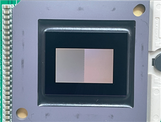
We have a homemade DLP670S PCBA.

It is possible that the DMD image is only half displayed.

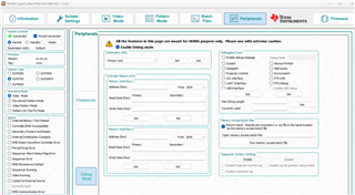
It remains the same even when using the TI GUI. This problem cannot be solved using the s reset button. If it continues to be triggered, the status bar "Sequencer Operation" will be interrupted.

Sometimes, the system operates normally after being powered off and back on, but the above problems may still occur.

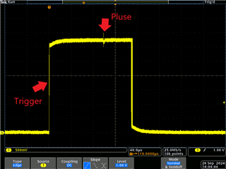
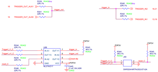
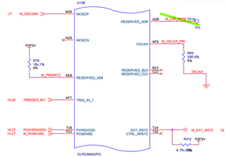
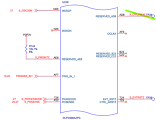
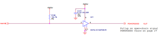
Use an oscilloscope to observe Trigger In1.

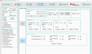
When switching GUI mode, will see a small pulses.

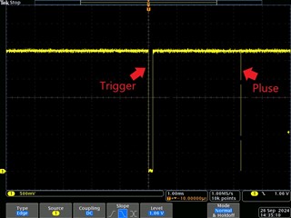
When our triggered, there will also be a small pulse after a while.

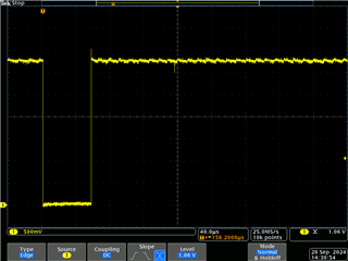
The same thing happens even if the trigger is inverted or add width.

Using pull-down resistors is still the same.

  • Hello James,

    Thank you for coming to E2E!

    The DLP670S utilizes a dual DLPC900 controller chipset to control both sides of the DMD. Could you please advise that you have compared your design with the DLPLCRC900DEVM? This should show if there are any design differences.

    Please advise if pin V26 is set correctly as the primary/secondary ASICs are set with this pin.

    Best,

    Aaron

  • Hi Aaron,

    I have compared with evm.

    The difference lies in the picture below.

    We've produced a small batch.

    This issue occurs only on this board.

    The pins on the master-slave device have been configured.

    I have adjusted the series resistor,

    and increased the pull-down resistor, similar to the EVM.

    Both has reduced the likelihood of interruptions.

    However, sporadic interruption and some small pulses still remain.

    Best,

    James

  • Hello James,

    You say,

    This issue occurs only on this board.

    Is this the half-image issue and is it only seen on 1 of your small batch?

    Also, how does the Trigger1_o1_c look like it's connected?

    Best,

    Aaron 

  • Hello James,

    Those pulses are expected as they match roughly the same timing as reset (mirror clocking pulse) signals, which can be induced by nearby traces.

    I am still concerned about your output trigger because the 2 output triggers are not utilized in the same fashion and do not have the same output waveforms.

    You are logically able to get away with tying the input trigger 1 and 2 because using Pattern-on-the-fly or pre-stored pattern modes BUT you can ONLY see the first pattern and hindering yourself from advancing to more than 1 pattern. The best thing to do is to split the traces and  ground Trigger in 2 and in software invert Trigger 2 you have grounded.

    Best,

    Aaron

  • Hello Aaron,
    Thank you for your reply and suggestions.
    Yes,it is only seen on 1 of our small batch.
    When the half-image occurs, "reset_C" and "Trigger1_o1_c" are not connected to anything.
    Is it still possible that this is caused by nearby reset traces?
    We sincerely appreciate your suggestion and Trigger IN 1 and 2 will be correction in next version.
    Best,
    James

  • Hey James,

    Can you send how the Trigger1_o1_c are connected? From what you've shared they look to be connected.

    Because it is a half-image file, I am leaning towards this being isolated to one of the DLPC900 controllers or data lines to/from the DMD.

    Have you tried replacing this DLP670S DMD between a working system and this one? Does the DMD continue to show issues on a different system?

    Best,

    Aaron

  • Hello Aaron,

    Yes, I have tested this DMD in another system and it is functioning normally.

    The Trigger_out is connected to the Master DLPC900 Trigger_out1 (E20).

    The TriggerI_o1_C and reset_C (J40 Connector Pin3 and Pin2) are unconnected.

    The TriggerI_i1_C and GND (J40 Connector Pin1 and Pin4) are connected to MCU (using NL37WZ17) with cable.

    Best,
    James

  • Hello James,

    Thank you for the images! It is also best practice for the Trigger out signals to not be tied even if trigger 1 is inverted and there is no dark time (always low) because this is not tested and might have issues over time, in the immediate time, the peripheral device that is connected to trigger out may not be receiving the appropriate voltage signal.

    The half-image issue seems that one of your controllers is not reliably being initializing. Please share a photo of the DMD array during this time half-image operation.

    Additionally, the GUI might be able to identify the error and narrow down to which controller. Please utilize the GUI and make note of the status bar on the left under Operating Mode. You can additionally go to the 'Peripheral' tab and go to 'Debug Mode' and enable debug mode. If you select 'Primary only' or 'Secondary only' and perform a 'SET' the Status box on the left will change accordingly. Please advise what the status is for both Primary and Secondary when you are seeing the half-image issue.

    I have this set up with a Virtual Connection but this is close to what it will look like on the GUI:

    Best,

    Aaron 

  • Hello Aaron,

    Thank you for your reply.

    Trigger out and Trigger in will be separated using different components in the next version.

    Following the method you suggested,

    I observed that Secondary "Sequencer Abort Status Flag Error" is ticked on the status bar.

    Please download related videos from the link below

    Video Link:

    https://drive.google.com/file/d/14SWwweaD4s7AqYTWrptnzZqTjv-6pAfX/view?usp=drive_link

    Best,
    James

  • Hello James,

    Sorry, I cannot access the video you sent through Google Drive. If you would like to, please upload the files onto the TI drive - https://tidrive.itg.ti.com/a/Z60VCT0tFQx1rRUF/de4448ce-5c52-4205-9af1-a54877aafa5d?l

    I realize you are using a custom PCB but the error code you have shared is described in the EVM User's Guide, section 3.3 which states "Sequence Abort Status Flag – The box is checked whenever a sequence abort has occurred. Sequence abort may occur during any pattern mode in preparing a pattern sequence and the timing of reading the status. Additional status reads may be needed to get a correct state of this indicator. If the box continues to be checked, it could indicate an error condition in the pattern sequence."

    As I'm not sure what is in the videos yet, please also share the Pattern Settings page when you are experiencing this error.

    Best,

    Aaron

  • Hello James,

    In addition to Aaron's request, I have a few questions:

    1. Do you see the same behavior with other modes of operation like test pattern or images from flash?
    2. Are you using a flex cable to transfer data from the controller to DMD? We have seen such issues before, and most of the times, it is loosely connected flex cable.
    3. Do you have UART pins exposed on your board?

    Thank you,

    With regards,
    Aishwarya

  • Hello Aaron, Aishwarya,
    Thank you for your reply.
    Sorry, I cannot upload with the TI driver because the website is unable to be connected.
    I found the following link but can't log in.
    tidrive.ext.ti.com/.../

    Please refer to the Pattern Settings page below.

    1、Do you see the same behavior with other modes of operation like test pattern or images from flash?
    The "Pre-stored Pattern Mode" happened and can also occur when utilizing images from flash.
    2、Are you using a flex cable to transfer data from the controller to DMD? We have seen such issues before, and most of the times, it is loosely connected flex cable.
    We use FFC cables. I've replaced both connectors and cables, but the issue remains.
    I'll test other brands and update you.
    Do you have any other suggestions about this?
    3、Do you have UART pins exposed on your board?
    Please refer to the following for the information read by UART.

    Bootloader Version 4.2.0
    Jumping to application ...
    
    Debug opened on URT0
    Memory test cc = 1
    API version: 06.03.0
    App version: 06.03.0
    Configuration layout versions:
         Seq Map: 90.00.0001
         SW Map: 90.00.0000
    I2C Cmd Secondary Address 34
    IT653x - I2C_PolledPrimaryWrite failed 0:90:-7 in IT653x_Write 
    IT653x - I2C_PolledPrimaryWrite failed 0:90:-7 in IT653x_Write 
    IT653x - I2C_PolledPrimaryWrite failed 0:90:-7 in IT653x_Write 
    IT653x - I2C_PolledPrimaryWrite failed 0:90:-7 in IT653x_Write 
    IT653x - I2C_PolledPrimaryWrite failed 0:90:-7 in IT653x_Write 
    IT653x - I2C_PolledPrimaryWrite failed 0:90:-7 in IT653x_Write 
    IT653x - I2C_PolledPrimaryWrite failed 0:90:-7 in IT653x_Write 
    IT653x - I2C_PolledPrimaryWrite failed 0:90:-7 in IT653x_Write 
    IT653x - I2C_PolledPrimaryWriteRestartRead failed 0:B5:90:-7 in IT653x_Read 
    IT653x - I2C_PolledPrimaryWrite failed 0:90:-7 in IT653x_Write 
    IT653x - I2C_PolledPrimaryWriteRestartRead failed 0:B2:B0:-7 in IT653x_Read 
    IT653x - I2C_PolledPrimaryWrite failed 0:B0:-7 in IT653x_Write 
    IT653x - I2C_PolledPrimaryWriteRestartRead failed 0:B5:90:-7 in IT653x_Read 
    IT653x - I2C_PolledPrimaryWrite failed 0:90:-7 in IT653x_Write 
    IT653x - I2C_PolledPrimaryWriteRestartRead failed 0:B5:90:-7 in IT653x_Read 
    IT653x - I2C_PolledPrimaryWrite failed 0:90:-7 in IT653x_Write 
    IT653x - I2C_PolledPrimaryWriteRestartRead failed 0:A9:90:-7 in IT653x_Read 
    IT653x - I2C_PolledPrimaryWriteRestartRead failed 0:B5:90:-7 in IT653x_Read 
    IT653x - I2C_PolledPrimaryWrite failed 0:90:-7 in IT653x_Write 
    IT653x - I2C_PolledPrimaryWriteRestartRead failed 0:B5:90:-7 in IT653x_Read 
    IT653x - I2C_PolledPrimaryWriteRestartRead failed 0:B5:90:-7 in IT653x_Read 
    IT653x - I2C_PolledPrimaryWrite failed 0:90:-7 in IT653x_Write 
    IT653x - I2C_PolledPrimaryWriteRestartRead failed 0:89:C0:-7 in IT653x_Read 
    IT653x - I2C_PolledPrimaryWrite failed 0:C0:-7 in IT653x_Write 
    IT653x - I2C_PolledPrimaryWrite failed 0:90:-7 in IT653x_Write 
    IT653x - I2C_PolledPrimaryWrite failed 0:90:-7 in IT653x_Write 
    IT653x - I2C_PolledPrimaryWrite failed 0:90:-7 in IT653x_Write 
    IT653x - I2C_PolledPrimaryWrite failed 0:C0:-7 in IT653x_Write 
    IT653x - I2C_PolledPrimaryWriteRestartRead failed 0:07:C0:-7 in IT653x_Read 
    IT653x - I2C_PolledPrimaryWrite failed 0:C0:-7 in IT653x_Write 
    IT653x - I2C_PolledPrimaryWrite failed 0:90:-7 in IT653x_Write 
    IT653x - I2C_PolledPrimaryWriteRestartRead failed 0:B5:90:-7 in IT653x_Read 
    IT653x - I2C_PolledPrimaryWriteRestartRead failed 0:B5:90:-7 in IT653x_Read 
    IT653x - I2C_PolledPrimaryWrite failed 0:90:-7 in IT653x_Write 
    IT653x - I2C_PolledPrimaryWrite failed 0:90:-7 in IT653x_Write 
    IT653x - I2C_PolledPrimaryWrite failed 0:90:-7 in IT653x_Write 
    IT653x - I2C_PolledPrimaryWrite failed 0:90:-7 in IT653x_Write 
    IT653x - I2C_PolledPrimaryWriteRestartRead failed 0:05:B0:-7 in IT653x_Read 
    IT653x - I2C_PolledPrimaryWrite failed 0:B0:-7 in IT653x_Write 
    IT653x - I2C_PolledPrimaryWriteRestartRead failed 0:C9:B0:-7 in IT653x_Read 
    IT653x - I2C_PolledPrimaryWrite failed 0:B0:-7 in IT653x_Write 
    IT653x - I2C_PolledPrimaryWriteRestartRead failed 0:CF:B0:-7 in IT653x_Read 
    IT653x - I2C_PolledPrimaryWrite failed 0:B0:-7 in IT653x_Write 
    IT653x - I2C_PolledPrimaryWriteRestartRead failed 0:05:B0:-7 in IT653x_Read 
    IT653x - I2C_PolledPrimaryWrite failed 0:B0:-7 in IT653x_Write 
    IT653x - I2C_PolledPrimaryWriteRestartRead failed 0:A2:B0:-7 in IT653x_Read 
    IT653x - I2C_PolledPrimaryWrite failed 0:B0:-7 in IT653x_Write 
    IT653x - I2C_PolledPrimaryWriteRestartRead failed 0:B1:B0:-7 in IT653x_Read 
    IT653x - I2C_PolledPrimaryWrite failed 0:B0:-7 in IT653x_Write 
    IT653x - I2C_PolledPrimaryWriteRestartRead failed 0:B1:B0:-7 in IT653x_Read 
    IT653x - I2C_PolledPrimaryWrite failed 0:B0:-7 in IT653x_Write 
    IT653x - I2C_PolledPrimaryWriteRestartRead failed 0:B2:B0:-7 in IT653x_Read 
    IT653x - I2C_PolledPrimaryWrite failed 0:B0:-7 in IT653x_Write 
    IT653x - I2C_PolledPrimaryWriteRestartRead failed 0:D3:B0:-7 in IT653x_Read 
    IT653x - I2C_PolledPrimaryWrite failed 0:B0:-7 in IT653x_Write 
    IT653x - I2C_PolledPrimaryWriteRestartRead failed 0:D2:B0:-7 in IT653x_Read 
    IT653x - I2C_PolledPrimaryWrite failed 0:B0:-7 in IT653x_Write 
    IT653x - I2C_PolledPrimaryWriteRestartRead failed 0:05:B0:-7 in IT653x_Read 
    IT653x - I2C_PolledPrimaryWrite failed 0:B0:-7 in IT653x_Write 
    IT653x - I2C_PolledPrimaryWriteRestartRead failed 0:ED:B0:-7 in IT653x_Read 
    IT653x - I2C_PolledPrimaryWrite failed 0:B0:-7 in IT653x_Write 
    IT653x - I2C_PolledPrimaryWrite failed 0:90:-7 in IT653x_Write 
    IT653x - I2C_PolledPrimaryWriteRestartRead failed 0:B5:90:-7 in IT653x_Read 
    IT653x - I2C_PolledPrimaryWrite failed 0:90:-7 in IT653x_Write 
    IT653x - I2C_PolledPrimaryWriteRestartRead failed 0:B5:90:-7 in IT653x_Read 
    IT653x - I2C_PolledPrimaryWrite failed 0:90:-7 in IT653x_Write 
    IT653x - I2C_PolledPrimaryWrite failed 0:C0:-7 in IT653x_Write 
    IT653x - I2C_PolledPrimaryWriteRestartRead failed 0:07:C0:-7 in IT653x_Read 
    IT653x - I2C_PolledPrimaryWrite failed 0:C0:-7 in IT653x_Write 
    IT653x - I2C_PolledPrimaryWrite failed 0:90:-7 in IT653x_Write 
    IT653x - I2C_PolledPrimaryWrite failed 0:90:-7 in IT653x_Write 
    IT653x - I2C_PolledPrimaryWrite failed 0:90:-7 in IT653x_Write 
    IT653x - I2C_PolledPrimaryWrite failed 0:90:-7 in IT653x_Write 
    IT653x - I2C_PolledPrimaryWrite failed 0:90:-7 in IT653x_Write 
    IT653x - I2C_PolledPrimaryWrite failed 0:C0:-7 in IT653x_Write 
    IT653x - I2C_PolledPrimaryWrite failed 0:C0:-7 in IT653x_Write 
    IT653x - I2C_PolledPrimaryWrite failed 0:C0:-7 in IT653x_Write 
    IT653x - I2C_PolledPrimaryWrite failed 0:C0:-7 in IT653x_Write 
    IT653x - I2C_PolledPrimaryWrite failed 0:C0:-7 in IT653x_Write 
    IT653x - I2C_PolledPrimaryWrite failed 0:C0:-7 in IT653x_Write 
    IT653x - I2C_PolledPrimaryWrite failed 0:C0:-7 in IT653x_Write 
    IT653x - I2C_PolledPrimaryWriteRestartRead failed 0:05:B0:-7 in IT653x_Read 
    IT653x - I2C_PolledPrimaryWriteRestartRead failed 0:05:B0:-7 in IT653x_Read 
    IT653x - I2C_PolledPrimaryWrite failed 0:B0:-7 in IT653x_Write 
    IT653x - I2C_PolledPrimaryWriteRestartRead failed 0:EF:B0:-7 in IT653x_Read 
    IT653x - I2C_PolledPrimaryWrite failed 0:B0:-7 in IT653x_Write 
    IT653x - I2C_PolledPrimaryWrite failed 0:C0:-7 in IT653x_Write 
    IT653x - I2C_PolledPrimaryWrite failed 0:C0:-7 in IT653x_Write 
    IT653x - I2C_PolledPrimaryWrite failed 0:C0:-7 in IT653x_Write 
    IT653x - I2C_PolledPrimaryWrite failed 0:C0:-7 in IT653x_Write 
    IT653x - I2C_PolledPrimaryWrite failed 0:C0:-7 in IT653x_Write 
    IT653x - I2C_PolledPrimaryWrite failed 0:C0:-7 in IT653x_Write 
    IT653x - I2C_PolledPrimaryWrite failed 0:C0:-7 in IT653x_Write 
    IT653x - I2C_PolledPrimaryWrite failed 0:C0:-7 in IT653x_Write 
    IT653x - I2C_PolledPrimaryWrite failed 0:C0:-7 in IT653x_Write 
    IT653x - I2C_PolledPrimaryWrite failed 0:C0:-7 in IT653x_Write 
    IT653x - I2C_PolledPrimaryWrite failed 0:C0:-7 in IT653x_Write 
    IT653x - I2C_PolledPrimaryWrite failed 0:C0:-7 in IT653x_Write 
    IT653x - I2C_PolledPrimaryWrite failed 0:C0:-7 in IT653x_Write 
    IT653x - I2C_PolledPrimaryWrite failed 0:C0:-7 in IT653x_Write 
    IT653x - I2C_PolledPrimaryWrite failed 0:C0:-7 in IT653x_Write 
    IT653x - I2C_PolledPrimaryWrite failed 0:C0:-7 in IT653x_Write 
    IT653x - I2C_PolledPrimaryWrite failed 0:C0:-7 in IT653x_Write 
    IT653x - I2C_PolledPrimaryWrite failed 0:C0:-7 in IT653x_Write 
    IT653x - I2C_PolledPrimaryWriteRestartRead failed 0:3D:C0:-7 in IT653x_Read 
    IT653x - I2C_PolledPrimaryWriteRestartRead failed 0:19:C0:-7 in IT653x_Read 
    IT653x - I2C_PolledPrimaryWrite failed 0:C0:-7 in IT653x_Write 
    IT653x - I2C_PolledPrimaryWriteRestartRead failed 0:04:C0:-7 in IT653x_Read 
    IT653x - I2C_PolledPrimaryWrite failed 0:C0:-7 in IT653x_Write 
    IT653x - I2C_PolledPrimaryWriteRestartRead failed 0:9B:C0:-7 in IT653x_Read 
    IT653x - I2C_PolledPrimaryWrite failed 0:C0:-7 in IT653x_Write 
    IT653x - I2C_PolledPrimaryWrite failed 0:C0:-7 in IT653x_Write 
    IT653x - I2C_PolledPrimaryWrite failed 0:C0:-7 in IT653x_Write 
    IT653x - I2C_PolledPrimaryWrite failed 0:C0:-7 in IT653x_Write 
    IT653x - I2C_PolledPrimaryWrite failed 0:C0:-7 in IT653x_Write 
    IT653x - I2C_PolledPrimaryWrite failed 0:C0:-7 in IT653x_Write 
    IT653x - I2C_PolledPrimaryWrite failed 0:C0:-7 in IT653x_Write 
    IT653x - I2C_PolledPrimaryWrite failed 0:C0:-7 in IT653x_Write 
    IT653x - I2C_PolledPrimaryWrite failed 0:C0:-7 in IT653x_Write 
    IT653x - I2C_PolledPrimaryWrite failed 0:C0:-7 in IT653x_Write 
    IT653x - I2C_PolledPrimaryWrite failed 0:C0:-7 in IT653x_Write 
    IT653x - I2C_PolledPrimaryWrite failed 0:C0:-7 in IT653x_Write 
    IT653x - I2C_PolledPrimaryWrite failed 0:C0:-7 in IT653x_Write 
    IT653x - I2C_PolledPrimaryWrite failed 0:C0:-7 in IT653x_Write 
    IT653x - I2C_PolledPrimaryWrite failed 0:C0:-7 in IT653x_Write 
    IT653x - I2C_PolledPrimaryWrite failed 0:C0:-7 in IT653x_Write 
    IT653x - I2C_PolledPrimaryWrite failed 0:C0:-7 in IT653x_Write 
    IT653x - I2C_PolledPrimaryWrite failed 0:C0:-7 in IT653x_Write 
    IT653x - I2C_PolledPrimaryWrite failed 0:C0:-7 in IT653x_Write 
    IT653x - I2C_PolledPrimaryWrite failed 0:C0:-7 in IT653x_Write 
    IT653x - I2C_PolledPrimaryWrite failed 0:C0:-7 in IT653x_Write 
    IT653x - I2C_PolledPrimaryWrite failed 0:C0:-7 in IT653x_Write 
    IT653x - I2C_PolledPrimaryWrite failed 0:C0:-7 in IT653x_Write 
    IT653x - I2C_PolledPrimaryWrite failed 0:C0:-7 in IT653x_Write 
    IT653x - I2C_PolledPrimaryWrite failed 0:C0:-7 in IT653x_Write 
    IT653x - I2C_PolledPrimaryWrite failed 0:C0:-7 in IT653x_Write 
    IT653x - I2C_PolledPrimaryWrite failed 0:C0:-7 in IT653x_Write 
    IT653x - I2C_PolledPrimaryWrite failed 0:C0:-7 in IT653x_Write 
    IT653x - I2C_PolledPrimaryWrite failed 0:C0:-7 in IT653x_Write 
    IT653x - I2C_PolledPrimaryWrite failed 0:C0:-7 in IT653x_Write 
    IT653x - I2C_PolledPrimaryWrite failed 0:C0:-7 in IT653x_Write 
    IT653x - I2C_PolledPrimaryWrite failed 0:C0:-7 in IT653x_Write 
    IT653x - I2C_PolledPrimaryWrite failed 0:C0:-7 in IT653x_Write 
    IT653x - I2C_PolledPrimaryWrite failed 0:C0:-7 in IT653x_Write 
    IT653x - I2C_PolledPrimaryWrite failed 0:C0:-7 in IT653x_Write 
    IT653x - I2C_PolledPrimaryWriteRestartRead failed 0:07:C0:-7 in IT653x_Read 
    IT653x - I2C_PolledPrimaryWrite failed 0:C0:-7 in IT653x_Write 
    IT653x - I2C_PolledPrimaryWrite failed 0:C0:-7 in IT653x_Write 
    IT653x - I2C_PolledPrimaryWriteRestartRead failed 0:73:C0:-7 in IT653x_Read 
    IT653x - I2C_PolledPrimaryWrite failed 0:C0:-7 in IT653x_Write 
    digcontrol_init complete: 1
    Secondary ASIC is  Ready (0).
    thinapp : Goto State : 3 0
    ARM memory pool 00000000 00100000
    DRAM memory pool 2000F1E8 000F0E18
    Autolock initialization passed 
    Picture Control: Default System Mode 0 
    thinapp : Display mode 1 0
    Displaying Video Curtain...
    Illumination: Transition to operating mode
     Configuring LED Enable and PWM Driver...
     PWM Driver initialized...
     Setting PWM Drive Levels...
    Controller Product ID: 06
    DMD Type: 74
    Fuse bits - dmdBuf[10]: CC
    System Mode: There are 1 defined System Modes 
    System Mode: System Mode 0 supports 2D 
    Sysmon: Executing Default Batch file
    thinapp : Goto State : 11 1
    thinapp : Display mode 2 -1
    Displaying Dummy Splash Image
    Index = 0 Imageindex = 0 Bitindex = 0
     Index = 1 Imageindex = 0 Bitindex = 8
     Index = 2 Imageindex = 0 Bitindex = 16
     Index = 3 Imageindex = 1 Bitindex = 0
     Index = 4 Imageindex = 1 Bitindex = 8
     Index = 5 Imageindex = 1 Bitindex = 16
     Index = 6 Imageindex = 2 Bitindex = 0
     Index = 7 Imageindex = 2 Bitindex = 8
     Index = 8 Imageindex = 2 Bitindex = 16
     Index = 9 Imageindex = 3 Bitindex = 0
     Index = 10 Imageindex = 3 Bitindex = 8
     Index = 11 Imageindex = 3 Bitindex = 16
     Index = 12 Imageindex = 4 Bitindex = 0
     Index = 13 Imageindex = 4 Bitindex = 8
     Index = 14 Imageindex = 4 Bitindex = 16
     Index = 15 Imageindex = 5 Bitindex = 0
     Index = 16 Imageindex = 5 Bitindex = 8
     Index = 17 Imageindex = 5 Bitindex = 16
     Index = 18 Imageindex = 6 Bitindex = 0
     Index = 19 Imageindex = 6 Bitindex = 8
     Index = 20 Imageindex = 6 Bitindex = 16
     Index = 21 Imageindex = 7 Bitindex = 0
     Index = 22 Imageindex = 7 Bitindex = 8
     Index = 23 Imageindex = 7 Bitindex = 16
     thinapp : System Powerup complete
    Total dynamic memory used 0xC228
    
    Bootloader Version 4.2.0
    Jumping to application ...
    
    Debug opened on URT0
    Memory test cc = 1
    API version: 06.03.0
    App version: 06.03.0
    Configuration layout versions:
         Seq Map: 90.00.0001
         SW Map: 90.00.0000
    I2C Cmd Secondary Address 34
    thinapp : Goto State : 3 0
    ARM memory pool 00000000 00100000
    DRAM memory pool 2000F1E8 000F0E18
    Autolock initialization passed 
    Picture Control: Default System Mode 0 
    thinapp : Display mode 1 0
    Displaying Video Curtain...
    Illumination: Transition to operating mode
    Controller Product ID: 06
    System Mode: There are 1 defined System Modes 
    System Mode: System Mode 0 supports 2D 
    Sysmon: Executing Default Batch file
    thinapp : Goto State : 11 1
    thinapp : Display mode 2 -1
    Displaying Dummy Splash Image
    Index = 0 Imageindex = 0 Bitindex = 0
     Index = 1 Imageindex = 0 Bitindex = 8
     Index = 2 Imageindex = 0 Bitindex = 16
     Index = 3 Imageindex = 1 Bitindex = 0
     Index = 4 Imageindex = 1 Bitindex = 8
     Index = 5 Imageindex = 1 Bitindex = 16
     Index = 6 Imageindex = 2 Bitindex = 0
     Index = 7 Imageindex = 2 Bitindex = 8
     Index = 8 Imageindex = 2 Bitindex = 16
     Index = 9 Imageindex = 3 Bitindex = 0
     Index = 10 Imageindex = 3 Bitindex = 8
     Index = 11 Imageindex = 3 Bitindex = 16
     Index = 12 Imageindex = 4 Bitindex = 0
     Index = 13 Imageindex = 4 Bitindex = 8
     Index = 14 Imageindex = 4 Bitindex = 16
     Index = 15 Imageindex = 5 Bitindex = 0
     Index = 16 Imageindex = 5 Bitindex = 8
     Index = 17 Imageindex = 5 Bitindex = 16
     Index = 18 Imageindex = 6 Bitindex = 0
     Index = 19 Imageindex = 6 Bitindex = 8
     Index = 20 Imageindex = 6 Bitindex = 16
     Index = 21 Imageindex = 7 Bitindex = 0
     Index = 22 Imageindex = 7 Bitindex = 8
     Index = 23 Imageindex = 7 Bitindex = 16
     thinapp : System Powerup complete
    Total dynamic memory used 0xC228
    

  • Hello James,

    Thank you for sending over your videos! I was not sure where/when this error was happening and I should be able to try and replicate this error.

    While I am doing this, please do keep us updated on alternate FFC connections.

    Best,

    Aaron

  • Hey James,

    After looking through your information we should have good information!

    You've shown that trigger in 2 is defined as non-inverted. We've noted that this is susceptible to noise as this is acting as a gate to advance the pattern, and when this is activated at the same time as the trigger input 1 unexpected behavior has been seen.

    I'm unable to test this currently but I have a coworker who is testing this.

    Unfortunately, you will not be able to see this in your current build, but in your future build when all trigger out and trigger in lines are separate you can set the trigger 2 to inverted, advancing the pattern when low, and this will be more stable for you in pattern generation.

    Best,

    Aaron

  • Hello Aaron,

    Although Trigger_IN1 and Trigger_IN2 are designed the same trigger in the circuit,

    only Trigger_IN1 is actually used because R340 is not installed.

    Regarding the previously mentioned test of replacing the connector of other brands,

    I have already tested it and the problem still exists.

    Best,

    James

  • Hello James,

    I think there is some confusion here about Trigger in 2.

    At no time can we leave this floating or any other trigger lines, you will need to do the below to get the most reasonable solution for a single trigger input:

    1. Ground connection from trigger in 2 to the board GND
    2. Invert Trigger in 2 so it is constantly expecting a LOW

    With the Trigger in 2 floating the start or stop the pattern display has instability and I am not sure if that partly determines it has advanced the pattern display or not, it is not consistent behavior.

    Best,

    Aaron

  • Hello Aaron,

    Thank you for your help!

    Yesterday, I connected trigger in2 to ground and the small pulse disappeared.

    The burn-in observation has not revealed any abnormalities so far.

    It does seem like grounding is necessary, as you said.

    I will continue to observe.

    Thank you again.

    Best,

    James

  • Hello James,

    That's great to hear you have it working!

    I think this is your work-around for the time being. Please note that this is the easiest way to produce a single trigger-in connection and if your final board can be modified to offer this as a permanent solution, only if you will not need a 2nd trigger-in connection, you likely want to implement this change.

    I will close this thread for now and you may respond to the thread later or reference this thread in a future thread if need be.

    Please help me mark this as resolved.

    Best,

    Aaron