This thread has been locked.

If you have a related question, please click the "Ask a related question" button in the top right corner. The newly created question will be automatically linked to this question.

DLPLCRC900EVM: DLPLCRC900EVM

Part Number: DLPLCRC900EVM
Other Parts Discussed in Thread: DLPLCR65EVM

Tool/software:

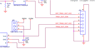
Hi. My DLPLCRC900EVM output is broken. There are no output signals from output1 and output2. It maybe caused by connecting the DMD output GNDs and DMD power GND as advised by the imaging camera tech. support. 

Before connecting the DMD output GND and DMD power GND, both output1 and output2 signals are normal. After we remove the DMD power GND connection with output GNDs, there are no signal detected anymore but DMD still works. How to fix the output? Do we need to repair the controller board? Thanks a lot. 

  • Hello Shiyuan,

    I'm sorry your system is not working, thank you for reaching out through E2E!

    Please advise how specifically the connection was created from DMD output GNDs and DMD power GND.

    Best,

    Aaron

  • Hello Shiyuan,

    Could you also advise which "Output" are you referring to? Is this a trigger or what?

    Best,

    Aaron

  • Sorry. Yes, the trigger output signal.

  • The DMD trigger output GND and DMD power GND was connected by a wire.

  • Hello Shiyuan,

    If the GNDs were connected while the system was off, this shouldn't be an issue as the controller and DMD boards should have a shared GND. If you were connecting the two while the system was operating there might have been damage done but again it doesn't seem likely.

    Which DMD EVM were you utilizing with the DLPLCRC900EVM (Single ASIC)? Where was DMD GND being connected exactly, do you have a Test Point or pin of a header?

    If you were connecting to the Output Trigger Port GND you should have used either pin 3 or 6 of J24, is that correct?

    Additionally, could you please advise what version of software you are working with and what DMD firmware?

    Best,

    Aaron

  • Yes, the controller board is  DLPLCRC900EVM (with DLPLCR65EVM). Power GND was connected to pin3 of J24, pin2 of J2 was used as the signal wire. We also connect power GND and pin6 of J24 when pin5/pin4 used as the signal wire. The trigger output signal was tested with an oscilloscope, and only background noise are detected. Since we have another brand new DLPLCRC900EVM (with DLPLCR65EVM), we did the same test on it with the oscilloscope and the intended trigger output signal was detected. The software version is 5.0.0. We are using the default fireware.

  • Hey Shiyuan,

    Again, the GND connections should be not be an issue if they're connected. I'm not sure what you're meaning by "signal wire". A diagram or photo would be helpful to understand how you have the connections setup but again, if they're using GND connections, this shouldn't be uncommon ground.

    You should update to the latest software (5.3.0) and firmware (6.3.0) for your EVM. You can find these on the DLPLCRC900EVM Product Page.

    Best,

    Aaron