This thread has been locked.

If you have a related question, please click the "Ask a related question" button in the top right corner. The newly created question will be automatically linked to this question.

DLP4621Q1EVM: Inquiry on ADC measurement at DLP230 Control Program

Part Number: DLP4621Q1EVM
Other Parts Discussed in Thread: LM3409

Tool/software:

Hi teams, 

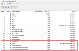
I would like to ask meaning of ADC measurements at DLP230 Control program. 

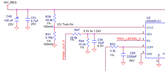
We're trying to modify DLP4621Q1EVM to drive laser diode, so that I would like to check ADC measurements which can be monitored at DLP230 Control program. 

Could you let us meaning of ADC measurements related to LED and which IC measures them?

ADC Measurements

IC

Pin

Description

LED_ANODE

TPS99000

ANC_IN1 ?

VLED

ILED Control DAC

TPS99000

IADJ ?

Photo Feedback Control DAC

TPS99000

TIA_PD1

Over-Brightness Control DAC

  • Jeremiah,

    https://www.ti.com/product/TPS99000-Q1

    Section 6.3.3 describes the ADC function in the TPS99000.  It will measure the input once per video frame.   How and what are you trying monitor more exactly?

    I have asked another colleague to assist.  Please note that most people are not in the office this week.

    Jason

  • Thanks for reply. Is it available that I know conversion equations of ADC measurement related to LED power?

    I'm trying to drive Laser diode whose forward voltage and current are ~17V and 2A with the development board based on DLP4621EVM's HL driver. 

    So if I know this meaning of conversion equation ADC measurements related to LED driving, it'll help for me to tune my design. 

    e.g. In case of that Vf = 17V and If = 2A, ADC measurements of VLED shall be 0.xxx.and ILED control DAC shall be 0.xxx

  • Jeremiah,

    The HL Driver board only support up to around 8-9V forward voltage for driving the LED or Laser.  The entire power supply scheme would need to modified to support higher driver voltage, the design would need to change to have a boost converter power supply.  The design assume today a 13V battery with dips down to ~9V or so.  In the case of 17V driver, the power supply would need to boost up the voltage to 18-19V.  

    The ADC sampling should occur to measure the Laser voltage indirectly.  For example, using a voltage divider to reduce the to range of 3V or so.

    Let us know if this makes sense.

    Jason

  • Thanks for your feedback. The borad which I'll modify is DLP006-001C_Headlight_LED_Driver which supports 16V and 6A max. Could you let us know how to supply 16V and 6A at DLP4621EVM? It could be measured with 14V and less than 1A with DLP4621EVM at this moment. This is because I'm not using ACP properly. 

  • Hi Jeremiah,

    The PWM (here as PWM0_OUT_F) generated from the DLPC230 is one factor in the average current output. The other is the resistor/capacitor network connected to the LM3409 on the IADJ pin. The COFF circuit will also have a small effect. I suggest you read the LM3409 datasheet to figure out the correct component values (here R47,R44,C54) for your application.

    https://www.ti.com/product/LM3409

  • Thanks for comment! I