DLP4710LC: Custom board based on DLP4710LC with dual DLPC3479 and DLPA3005.

Part Number: DLP4710LC
Other Parts Discussed in Thread: DLPC3479, DLPA3005

Tool/software:

Dear TI experts


We have a design based on your components for integration into our application of several thousand installations per year.
We designed our custom board based on the suggested reference designs for the DLP4710LC with dual DLPC3479 and DLPA3005.


We are currently using FW 8.3.0 with this design configuration:
DMD: DLP4710LC
Controller: DLPC3479
PMIC: DLPA3005
Illumination: 3-LED (RGB)
I2C address: 0x36
DMD pin mapping: Option 1

After the FW bootup phase the RESET_Z (1.8V) and INT_Z (2.4V) signals are high.
The initialization procedure is completed and we see on the N8 pins (HOST_IRQ) ​​of the DLPC3479 master and slave with high value on the connected LEDs.
At the output of the DLPA3005 we see the DMD supply voltages at 0V, specifically:
DMD_VRESET = 0V
DMD_VBIAS = 0V
DMD_VOFFSET = 0V
Furthermore the VLED signal remains with a value of 0.9V

We also tested the environment with the latest available version of the FW 8.4.0 but with the same effects.
We will focus on version 8.3.0 for now


What can we check to complete the validation of our board?

thanks in advance

  • Hello Amedeo,

    The person familiar with this platform is out of the office today, but is returning tomorrow.  I have assigned this inquiry to them.

    Fizix

  • Hello Amedeo,

    I will have to test this. Please give me some time to test this for 8.4.0.

    The official EVM utilizes DMD Pin mapping Option 2. You can make your own board and follow pin mapping Option 1 as I assume you have done.

    The Firmware Selector Tool should have all the variations of the latest firmware and should be followed for any solutions. The updates are after bugs have been fixed and additional features are added, I unfortunately have not tested the the latest solution of your combination and will have to do so soon.

    If you are able to get 8.3.0 to work, I would recommend to continue your evaluation using the Pattern Sets you plan to use in your application. I'm sorry I can't tell your application.

    Best,

    Aaron

  • Hi Aaron Black,

    thanks for your feedback.


    It's no problem to adapt to the 8.3 option instead of the 8.4.
    For now the most blocking thing is that neither of them works on my board.


    What can I check to understand what blocking state my board is in? why at the output of the DLPA3005 we see the DMD supply voltage at 0V?

    thanks for your help

    Best,

    Amedeo

  • Hello Amedeo,

    Sorry I did not ask this earlier, where are you located? 

    Could you share a scope capture of the system power-up sequence? This would be the:

    1. System Power (12V)
    2. 5V Power Supply (preferably near the PMIC DLPA3005)
    3. 2.5V Power Supply (preferably near the PMIC DLPA3005)
    4. Project On (GPIO_08 from Primary ASIC also preferably near the DLPA3005)

    Best,

    Aaron

  • Hi Aaron,

    we are located in Switzerland.

    System Power is 19V.

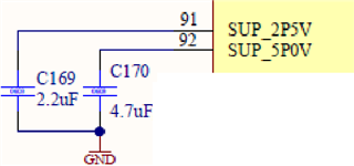
    As reported on the DLPA3005 datasheet: "The output capacitors of those LDOs should be 2.2 μF for the 2.5-V LDO, and 4.7 μF for the 5-V LDO, pin 91 and 92 respectively."

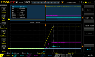
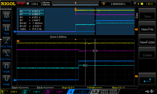
    I share the capture of the power-up sequence.

    yellow     SYSPWR
    blue     PROJ_ON
    purple     SUP_5P0V
    light blue    SUP_2P5V

    SUP_5P0V and SUP_2P5V rise to a precharge level with SYSPWR, and reach the full level potential after PROJ_ON is pulled high (4 seconds after SYSPWR my MCU raise PROJ_ON).

    thanks for your support

  • Hello Amedeo,

    Thank you for providing those so quickly!

    I need to discuss with my team shortly and I'll get back to you soon.

    Thank you for your patience!

    Best,

    Aaron

  • Hello Amedeo,

    I think I'll need to take a look at the design more in depth. Could you accept my connection and we'll take this offline.

    If there are updates I'll come back to this.

    Best,

    Aaron

  • Hello Aaron,

    Sure I will accept your connection but what exactly do I need to do?

    Best

    Amedeo

  • Hello Amedeo,

    I'll reach out to your further through private message. Thank you!

    Again, I'll keep this open to trace resolution after we come to a conclusion.

    Best,

    Aaron