DLPC4420AEVM: USB device disappear after a few seconds

Part Number: DLPC4420AEVM
Other Parts Discussed in Thread: DLP780TE, DLPC4420, , DLPA300

Tool/software:

Dear Sirs,

I am currently working with DLPC4420EVM to control a DLP780TE DMD. I followed the user manual instructions to set up the system, but I am encountering a critical issue during operation.

Issue Description:

  • When I power on the DLPC4420EVM, the USB device appears for a few seconds and allows me to communicate with the DMD via the DLPC44xx GUI.
  • However, after a few seconds, the screen goes black, the USB device disappears from Windows Device Manager, and I lose all control over the DMD.
  • During the short period when USB is active, I am able to load test patterns and make adjustments, but as soon as the USB disconnects, the DMD stops displaying any content.
  • The issue persists even when using different power supplies and USB cables.
  • I have already reflashed the firmware multiple times using Flash_DLPC4420_DLP780TE_xxx.img, but the issue remains the same.

Can you tell me what to do now?

Thanks for help.

Regards,

  • Hello David,

    Can you please confirm following questions:

    1. After power cycle the EVM, can you still see the image appears on the DMD for a few sections, then disappears? or the system cannot even power up?

    2. After re-programming the firmware, do you remove the jumper on J31?

    3. Do you turn off the switch SW1 before connecting the USB cable to DLPC4420AEVM?

    Regards,

    Lori 

  • Hello Lori,

    Thank you for your response. Please find my answers to your questions below:

    1. Yes, when I turn on SW1, I can see an image displayed on the DMD for a few seconds before it disappears. After the image disappears, I hear the USB disconnection sound from my computer, and after that, I am unable to control the DMD through the DLPC44xx GUI.

    2. Yes, after re-programming the firmware, I have removed the jumper on J31.

    3. Yes, I made sure to turn off SW1 before connecting the USB cable to the DLPC4420EVM.

    Please let me know if there are any further troubleshooting steps I should try. Thank you for your support!

    Best regards,
    David

  • I would like to provide some additional information to help clarify the issue:

    1. I have already tried using a different USB cable, but the issue persists.
    2. I have also tested the DLPC4420EVM on another PC to rule out any computer-related issues, but the same problem occurs.
    3. During the few seconds after turning on SW1, when the DMD displays the logo, I am able to establish communication with the DLPC44xx GUI and perform actions such as powering on/off the system and setting test patterns. However, when the logo disappears, I lose all control over the DMD.

    Please let me know if you need any further details or if there are additional troubleshooting steps I should try. I really appreciate your support!

    Best regards,
    David

  • Hello David,

    Thank you for the information!

    Can you please check the DMD power rails during power up and see if any of the power rails drop down when the image disappear on DMD?

    Please refer to DLP780TE datasheet section 7.4 Power Supply Recommendations and Figure 7-5. Measure and monitoring VDD, VDD1, VCC2, VMBRST.

    Regards,

    Lori 

  • Dear Lori,

    Thank you for your request.

    Below are the results:

    • VDD, VDD1: Remained stable at approximately 1.8V after power insertion, SW1 activation, and even after the image disappeared.
    • VCC2: Maintained at 10V after SW1 activation, but dropped to 0.3V after the image disappeared.
    • VMBRST: All measured values were within the Recommended Operating Conditions during  operation, but dropped to 0V after the image disappeared.

    From our observations, there was no significant drop in voltage in the power rails at the moment before the image disappeared.

    Please let us know if you need any further details or additional tests.

    Best regards,
    David

  • Hello David,

    I would suggest you checking the DLPA300 power up/down sequence and also checking the SCPEN, RESET and IRQ connections which connected to the fault logic block of the DLPA300.

    Please refer to section 8.2.3 on DLPA300 datasheet and share the waveforms you measured if you want. 

    Regards,

    Lori 

  • Hello Lori,

    Thank you for your response.

    I've attached the waveforms as follows:

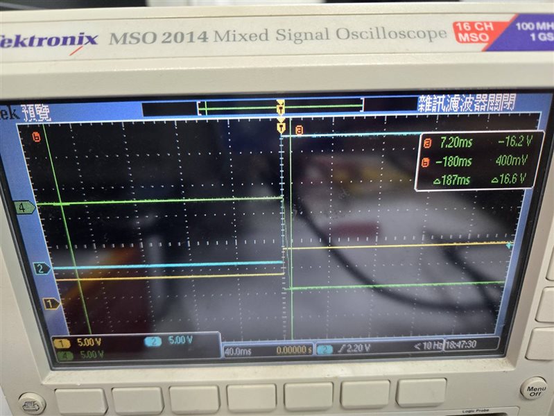
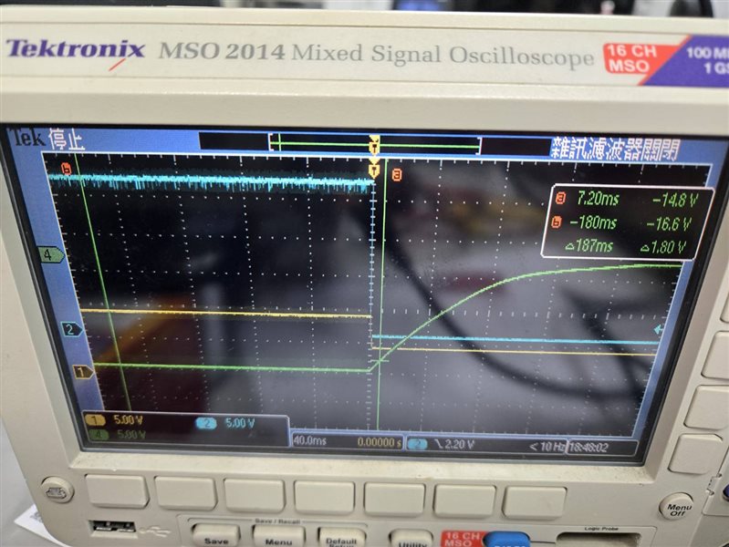
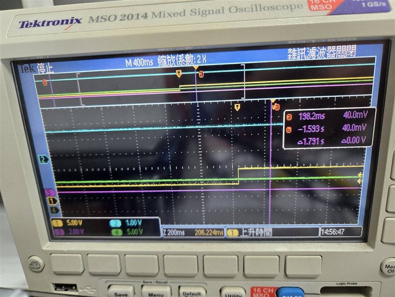
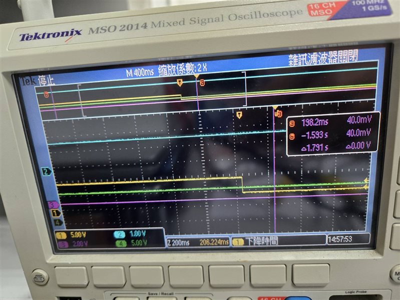
    • Figures 1 and 2 show the High Voltage Power-Up/Down Sequence.
    • CH1: VOFST
    • CH2: VBIAS
    • CH4: VRESET
    • DMD_RSTZ was not measured because I am unsure how to probe it.

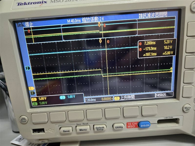
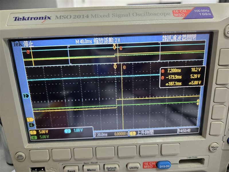
    • Figures 3 and 4 show the VCC2 Power-Up/Down Sequence.

      • CH1: VOFST
      • CH2: P1P8V
      • CH4: VCC2

    Currently, I am facing an issue where VCC2 suddenly remains constant at 10V without changing.

    Additionally, I measured SCPEN, RESET, and IRQ:

    • SCPEN and IRQ remain at 3.3V both before and after SW1 is turned on.
    • RESET is at 0V before SW1 is turned on, then stays at 3.3V until the logo disappears.

    Best regards,
    David

  • Hello Lori,

    I wanted to follow up with additional details regarding my measurement points, as I am not entirely sure if they were taken from the correct test points.

    • For Figures 1 and 2 (High Voltage Power-Up/Down Sequence):

      • CH1: Measured at TP24
      • CH2: Measured at TP26
      • CH4: Measured at TP25
    • For Figures 3 and 4 (VCC2 Power-Up/Down Sequence):

      • CH1: Measured at TP24
      • CH2: Measured at TP35 (on DLPC4420AEVM)
      • CH4: Measured at TP4

    Please let me know if these test points are appropriate, or if I should adjust my measurements.

    Best regards,
    David

  • Hello David,

    Thank you for providing the measurement! In your captures, I noticed that the Voffset starting at around 5V instead of 0V right? I'm not sure how this would happen, can you please zoom out the measurement and check if Voffset start at 0V and VCC2 can be captured at a pull up/down process, similar in Figure 8-4 and 8-5 in the DLPA300 datasheet? 

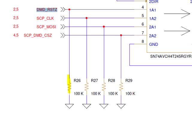
    For DMD_RSTZ, you can use R26 to probe. 

    Regards,

    Lori 

  • Hello Lori,

    I have expanded the time scale as requested, but I still cannot see VOFFSET starting from 0V. Additionally, I used a multimeter to verify the readings, and it confirms that both VOFFSET and VCC2 remain at 5V and 10V, respectively, immediately after power is connected.

    Let me know if you have any suggestions on what could be causing this behavior or if there are any additional measurements I should take.

    Best regards,
    David


  • Hi David,

    I need to investigate this and get back to you by the end of this week. 

    Regards,

    Lori 

  • Hello Lori,

    Thank you for your update. I appreciate your time investigating this, and I’ll wait for your feedback by the end of the week.

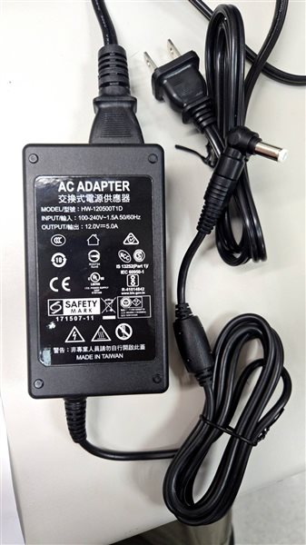
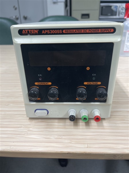
    Additionally, I have a question regarding the power supply configuration for DLPC4420EVM. Currently, we are using the power supply as shown in the attached image. If we want to switch to the alternative power supply shown in the second image, is there any other connection point on DLPC4420EVM to input power, or is J22 the only available option for power input?

    If J22 is the only valid connection, how should we properly connect the alternative power supply to ensure compatibility? Would you recommend this approach, or would it not be advisable due to potential issues?


    Best regards,
    David

  • Hello David,

    Yes, J22 is the only port for 12V input voltage on the EVM board. If you want to use the alternative DC power supply, you need to make sure the voltage and current meet the specs (Nominal voltage: 12V DC -5%/+10%; maximum output current: 7A). For the connection, please follow the design file and avoid any damage. 

    For the VOFFSET and VCC2 measurement, can you monitor and trigger the VOFFSET and VCC2 voltage level when 12V power is just applied? 

    Regards,

    Lori 

  • Hello Lori,

    Thank you for your guidance regarding the power supply connection.

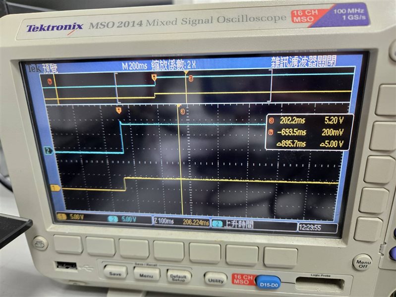
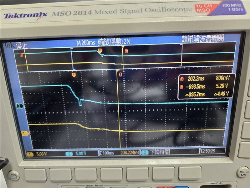
    Attached, please find the measurement results for VOFFSET and VCC2 during 12V power insertion and removal:

    • CH1 : VOFFSET
    • CH2 : VCC2

    Please let me know if you need further details or additional measurements.

    Best regards,
    David

  • Hi David,

    Thank you for the information!

    It looks like the VOFFSET pull up to a 5V level after 12V power is just applied and then from 5V to 10V after proj_on is applied. The expected behavior should be a 0V to 10V change when proj_on is applied. 

    I would like to confirm if this is the EVM you purchased from TI.com? Do you only have one EVM?

    If this is the EVM you purchased from TI.com, when did you buy it. The EVM has 90 days warranty.

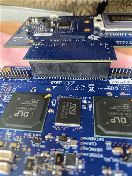
    Also, please double check all the connections, especially the DMD board need to stock all the way down with the controller board. Do you use any flex cable to connect DMD board and controller board?

    Regards,

    Lori 

  • Hello Lori,

    Yes, I purchased the EVM from TI.com approximately three weeks ago and received it two weeks ago. Currently, we only have this EVM. If a return or exchange is possible, please let me know the details. 

    Regarding the connections, our DMD and EVM are directly connected without any flex cable, and we have already reinstalled the connection. However, the issue persists.

    Best regards,
    David


  • Hello David,

    The problem could case by DLPA300 power up issue on the DLP780TE DMD board. Please request for RMA, you can reach out to your local distributor where you purchased the EVM. This thread can be used as proof of RMA authorization. 

    Regards,

    Lori