A related question is a question created from another question. When the related question is created, it will be automatically linked to the original question.
If you have a related question, please click the "Ask a related question" button in the top right corner. The newly created question will be automatically linked to this question.
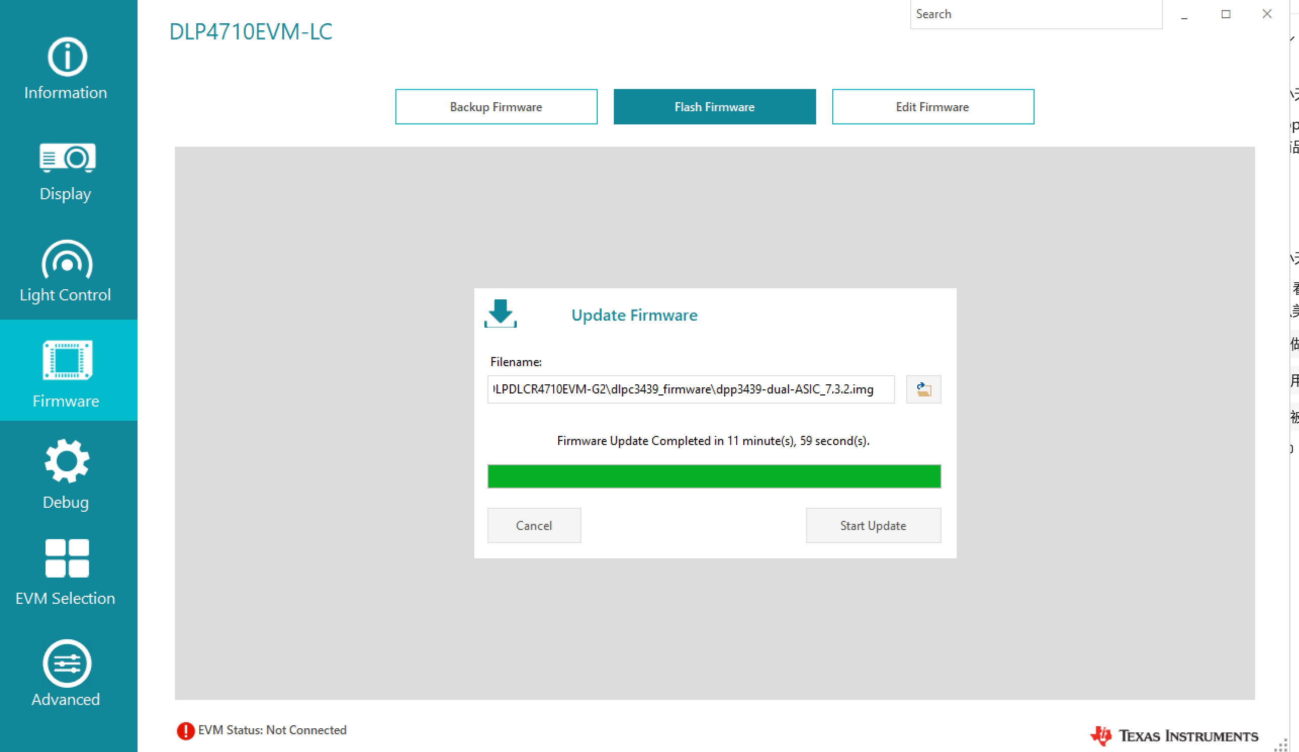
1. Should I reflash the firmware using the DLP LightCrafter Display software?
2, I opened the DLP LightCrafter Display, and then the EVM with USB, then switch on the power, I found it seems can't find any projector in the software
You are effectively connecting directly to flash IC and writing directly to it. This will require your PC, spi adapter, and clips to connect directly to flash.
intoboth the Master and the Slave flash. but thesame problem here. Could you check for me? thanks!
The verification process:
To make sure I've written successfully, I've read from the flash and saved thedatafile and attached here again.
There are 4 files in the zip file, 2 (mater and slave) are before writing to flash, 2 are after writing.
I've compared the 4 files and they are identical.
Also I compared them to the dpp3439-dual-ASIC_7.3.2.img file with Notepad++, and Notepad++ said it's identical, although the I noticed that the file size of dpp3439-dual-ASIC_7.3.2.img is 7,888 KB while the file read from the IC is 8192 KB.
I am wondering which one I should use? Also, when I learn to connect with I2C or RS-232, I can't find a PCB Layout file to ensure the GPIO1, GPIO2, GPIO6, or the I2C pins. Could you help point out the PCB layout file? Thanks!
Please disregard these files. There will need to be some pin configurations that may not be available to you on the EVM. Best way to recover the system would be the SOIC clip method.
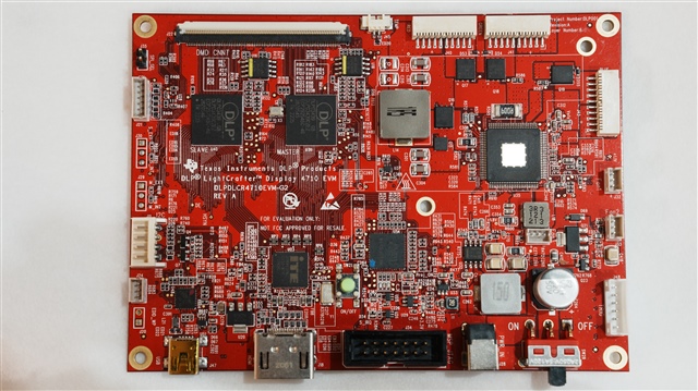
I've flashed DLPC34XX_BootDiagV1.0.0.img in by SPI, and now I'm stuck on how to get the diagnostic information out. Per the document, I should use a wire with USB(PC) to UART (EVM), but I don't know which interface I should use on the EVM board. Could you help?
GPIO 1 and 2 should be pulled high, meaning the output will go to HOST IRQ output pin. You can all read this signal from U25 on PIN 2 of the IC. U25 is located to the right of the green push button. It is a 5 pin leaded IC. You would connect your RX cable to this pin to get output from the firmware.