This thread has been locked.

If you have a related question, please click the "Ask a related question" button in the top right corner. The newly created question will be automatically linked to this question.

DLPC4430EVM: Issues about splash Image and test image

Part Number: DLPC4430EVM
Other Parts Discussed in Thread: DLP650LEEVM, DLPC4430, DLP650LE, DLPLCRC900EVM, DLPLCR55EVM

Tool/software:

Hello,

I am using dlpc4430evm and dlp650leevm. 

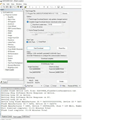
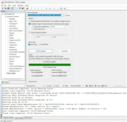
I checked 2.2.3 in the EVM User's Guide. Maybe, download is complete, but I cannot display the splash image. 

Several PCs, usb cables, and SW1 in both positions were tested. 

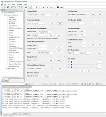
Instead, I tried to see if I can display a test pattern based on another forum post, but I am not able to do that either. 

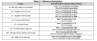
Do you have any advice on how to solve these issues? (e.g. jumper location for dlp650LEevm?)

Kind Regards,

Yuji

  • Hello Yuji,

    Please check following steps:

    1. Please check the jumpers are in the correct positions on the DLPC4430EVM. It also mentioned in section 2.2.2 of the EVM user's guide. J8 is the HOLD BL jumper, place this jumper when you programming the proper .img file. After programming successful, remove the jumper on J8. 

    2. Figure 2-2. ON/OFF Switch is not correct. In the image, switch up should be ON, switch down should be OFF. Please make sure the switch is ON when programming. 

    2. Do you use "Flash_DLPC4430_DLP650LE_p65_WXGA800_S450_LED.img" file? I cannot see in your screenshot. This is the correct image file for DLP650LEEVM.

    Regards,

    Lori 

  • Hello Lori,

    Thank you for the response.

    1. J8 is handled as described in the EVM user's guide.

    2. ON/OFF Switch is also checked.

    3. I am attaching my screenshot and log file for information. I think I am using the correct image.  

    Now I also noticed that the log file shows some usb errors when the download is complete. Is this related to the issue?

    Kind Regards,

    Yuji


     logfile.txt

  • Hello Yuji,

    Do you have the front end board connected with J1 on the DLPC4430EVM board? You need the front end board connected to display the image on the DMD. The default boot up image in the firmware is solidified, you should be able to change projection mode to test pattern or other modes. 

    Also, when you programming the board with image file, you can skip boot loader because the bootloader is pre-loaded on the board.

    In the screenshot, it looks like you have USB connection and was able to program .img file complete. Where do you notice the USB errors from the logfile? 

    Regards,

    Lori 

  • Hello Lori,

    Following your comments, I connected the front end board board to J1. Nothing can be displayed on the monitor connected to

    the front end board and the projection mode cannot be changed. If I try to change the mode, I get the following.

    Write Cmd:ProjectionMode, addr:34, subAddr:1 01 Write(OK) 

    Read Cmd:ProjectionMode, addr:35, subAddr:15 SendRead(FAILED(1))

    The GET button does not seem to be responding. 

    About the USB errors in my last reply, I was mentioning the information written in the log file.

    When the download completes, the log file is full of comments like "USB Errors: Transaction Request:

    USB Errors: 0000: 25 00 5d 48 00 78 00 28 06 d1 5c a1 01 20 c0 07". I thought these might be something wrong.

    Any information would be appreciated.

    Kind Regards,

    Yuji

  • Hello Yuji,

    If you have the front end board connected to J1, but without HDMI cable connected for external source, can you see the image on the DMD and switching projection mode work?

    It also could be the bootloader has been accidently programmed wrong. Then, you will need to use JTAG to program the bootloader. There is the JTAG Bootloader Programming Guide you can refer to which is inside of the DLPC4430AEVMSW download folder. 

    Please let me know if the issue can be fixed after reprogramming the bootloader. 

    Regards,

    Lori 

  • Hello Lori,

    When I connect the front end board to J1 without HDMI cable, I do not see any image on the DMD and the projection mode cannot be switched.

    I ordered the UM232H module and it will take some time to receive it. It has already been two weeks since I received the item. How can I get the product replaced as a warranty?

    Kind Regards,

    Yuji

  • Hi Yuji,

    The EVM has 90 days warranty. If you received with a damaged EVM or meet other return conditions, then you can start requesting for RMA. However, based on above information, I don't think the EVM is hardware damaged. I think the bootloader has been accidently programmed wrong, you should be able to fix the issue if you can reprogramming the bootloader. 

    For sanity check, can you please confirm the LED status when you connect the power supply (12-V DC, max 7A), and power up the EVM? Please also check if power up system voltage are correct, e.g. 1.1V, 1.8V, 3.3V, 12V.

    Regards,

    Lori 

  • Hello Lori,

    I don't see any particular problem with the LED status. I'll wait for the module to reprogram the bootloader.

    Kind Regards,

    Yuji

  • Thanks! Please let us know if you have further question.

    Regards,

    Lori 

  • Hello Lori,

    I completed Program Flash, but I am unable to verify Flash Contents.

    The situation has not changed.

     I have restarted the software and reconnected the cable.

    Kind Regards,

    Yuji

  • Hello Yuji,

    Please try to leave the Size(HEX) box blank and retry. Please see programming Guide procedure step 9 and 10. 

    You can use this E2E as reference if you see multiple devices showing in the JTAG Chain. https://e2e.ti.com/support/dlp-products-group/dlp/f/dlp-products-forum/1280314/dlplcrc900devm-jtag-flash-programmer-not-working/4855728?tisearch=e2e-sitesearch&keymatch=FT_PROG#4855728

    Regards,

    Lori 

  • Hello Lori,

    I have already checked the steps 9 and 10. The blank box for the Size (HEX) is just automatically written in, when programming is finished.

    I see only a single device.

    Kind Regards,

    Yuji

  • Hello Yuji,

    It seems like that you completed program flash, and the data mismatch address is small. I suspect when you verify flash contents, it compared the data already stored in with the programmed data. 

    I would suggest to use DLPC44XX GUI -> Flash Loader to reprogram the DLPC4430EVM image file with skip loot loader, and check if you can see image displayed on the DMD. 

    If you still cannot see image on the DMD, then go back to the bootloader programmer. Before programming bootloader, please erase all flash first, then follow the same steps to reprogram bootloader.

    Regards,

    Lori 

  • Hello Lori,

    I have tried what you pointed out and still nothing is showing up in the DMD.

    Kind Regards,
    Yuji

    (I am replying to the above content on behalf of the customer because tthere are some issues with the customer's posting)

  • Hello Yuji,

    For my point of view, if they programmed the bootloader successful and programmed the flash image file match the DLP650LE, and also confirmed the EVMs hardware are good, then I cannot tell what the issue is and it's hard to track each steps they have done. 

    Can you please share a picture of the boards and connections?

    Regards,

    Lori 

  • Hello Lori,

    Please find attached a photo.

    The molex connector is disconnected when checking operation.

    In addition, I recently purchased a combination of DLPLCRC900EVM and DLPLCR55EVM

    due to time constraints. For this combination, after updating the firmware, I have confirmed that it works.

    I would be grateful if you could check the detailed status of the product there.

    Kind Regards,
    Yuji


    Yuji

  • Hello Yuji,

    Please try to remove J8 jumper; change J9, J10, J11 jumpers to Pin 2 and 3;remove J40 and J41; make sure UM232H is not connected as you mentioned. 

    When you connect the 12V power supply, D9 and D10 Green LEDs should be ON; Then, switch SW1 to ON position, D15 Red LED should be ON for a second and OFF, D14 staring flashing. 

    Please also double check the LED status even you mentioned they are fine. 

    Regards,

    Lori 

  • Hello Lori,

    I have modified the positions of those jumpers without connecting UM232H. No particular change is seen.

    Regarding LEDs, D15 and D14 are not working. This occurred after JTAG programing.

    Kind Regards,
    Yuji

  • Hello Yuji,

    Did you see the LED operating the same as I mentioned above before programming JTAG? 

    It could be something wrong when you programing the JTAG. D14 and D15 are connected to 3.3 power. 

    Regards,

    Lori 

  • Hello Lori,

    I feel like the LED was working before. I have tested nearly all operational checks.

    Kind Regards,
    Yuji

  • Hi Yuji,

    If you can confirm that the LED was operating properly before programming the JTAG, then I would recommend you to reprogramming the JTAG one more time to make sure you have every steps included. As I mentioned above, once you have the JTAG programmed and program the flash image file to the EVM, and there is no damage on the hardware, then I could not think anything else I can help with.