This thread has been locked.

If you have a related question, please click the "Ask a related question" button in the top right corner. The newly created question will be automatically linked to this question.

DLP4620SQ1EVM: Error Code 0x2A2

Part Number: DLP4620SQ1EVM
Other Parts Discussed in Thread: TMP411

Tool/software:

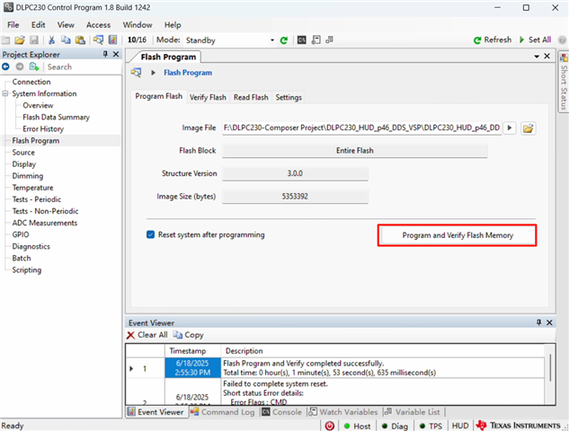
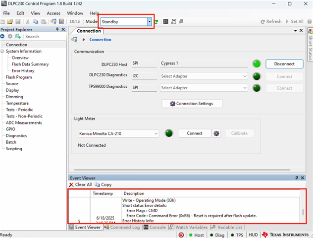
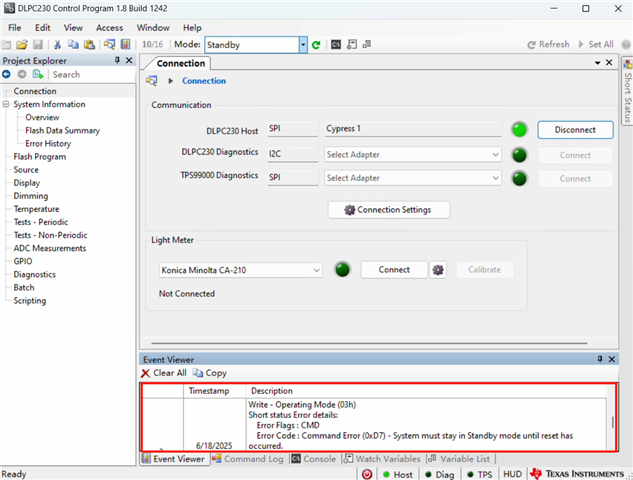
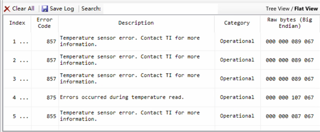
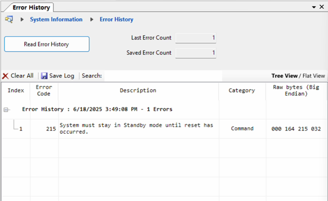
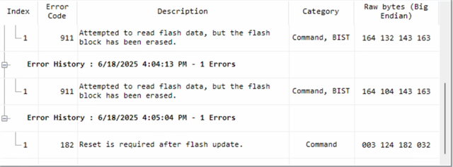
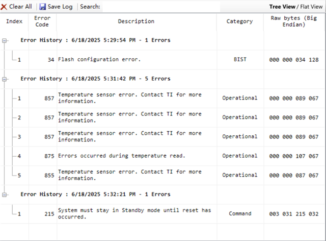
Currently, after connecting with HDMI, I encountered the following error while selecting External Video Port.May I restore the display without any errors?

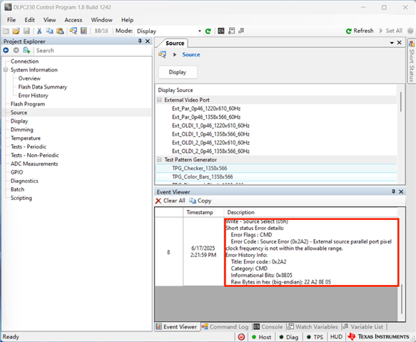
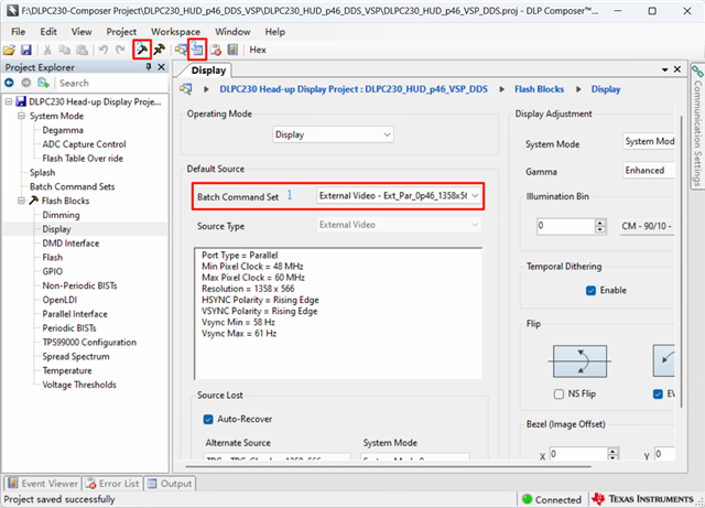
Secondly, I would like to ask, I understand that initialization displays the Test Pattern checkerboard as marked in Figure 1. However, if I want to switch to Mark 2 after connecting to HDMI and sending a command, how can I obtain the command or can I directly modify the initialization to lock Mark 2. Because I want to use my own control software but it is written in C++, operating Python files can be quite complicated. Can you provide any practical and feasible way to integrate operating instructions into my software
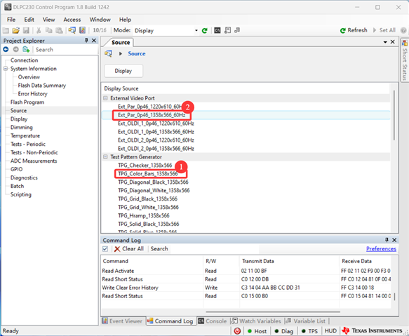
Thank you.

  • Hello again Cindy,

    For the first question. It looks like the refresh rate of the video input from the PC does not match the EDID programmed on the board. Can you please change the refresh rate on your PC to 59.96 Hz through 'Display Settings'.

    For the second question, you can generate firmware binaries with the help of DLP Composer tool. Using this you can set the startup display source as external video. Do you have access to this tool already?

    Unfortunately, we only provide python packages. You could either create a wrapper for these python APIs in your C++ software, or create your own C++ APIs for packet transfer by referring to the DLPC230 Programmer's Guide.

    Thank you,

    Regards,
    Aishwarya

  • Sorry,Aishwarya.I couldn't find it DLP Composer tool.I have only seen you mention it in a few other articles on the forum, but I feel that my problem has not yet delved so deeply. At the same time, I have found that the bin file for the basic configuration is as shown in the figure below. Can't I modify it on the most basic configuration? I feel that this will solve my problem of locking the configuration more quickly. Can you teach me how to operate it.

    Thank you,

    Cindy

  • If you need a secure access address for me, my email is yangxinyi@idteoe.com.

  • Could you release the access to the "DLP composer for automotive" about the configuration project files for Configuration File and the installation pack of "DLP composer for automotive"

    Thank you.

  • Hello Cindy,

    The Composer tool allows you to modify the .bin file. I have provided you access to download the tool.

    You can use the reference project from here - https://dev.ti.com/tirex/explore/node?node=A__AD2lliB9RuR9wRxGdyOSqQ__DLP-AUTOMOTIVE-BOARDS__FUz-xrs__LATEST

    I have also requested the local FAE to help you set up your system.

    Thank you,

    Regards,
    Aishwarya 

  • Hello Aishwarya,

    I have already placed The Composer tool.And I will modify the initialization configuration by following these steps. I hope to display the device when it is connected to HDMI instead of keeping the checkerboard image. But after configuring and burning the file, nothing can be displayed now. After flashing, my current also increased from 0.231A to 0.148A, which should be a problem with the DMD module. May I ask if I made a mistake while operating there.I found this project from the link you sent me.

  • I want to switch the status from standby to display, but the following error occurred

  • Cindy,

    Can you please share all the errors from the 'Error History' tab?

  • Sorry, I may have turned off the control pragram in the middle and only displayed Figure 1, but I flashed it again and it showed as Figure 2. Is there a problem with my previous configuration changes.

  • Cindy,

    Could you please clarify what is the error that you are seeing now? If it is only the error 215, could you please power-cycle the system and check again?
    Are you also seeing the error code 911?

    Regards,
    Aishwarya

  • Aishwarya,

    The error code I have received now is the following message.

    Cindy

  • Hi,Aishwarya
       I replied to you in the email you sent me. I don't know if you have seen it. The detailed follow-up and my confusion have been included in the email. I hope you can reply to me as soon as possible after seeing it. 
       I followed your steps to flash again, but when I tried to power it on again, the error still appeared. I checked the flexible cord and it was not damaged. But when I click read error again, it shows 0.
       Thank you,
       Cindy
  • Hi Cindy,

    May you please check which TMP411 you have? There is TMP411A, TMP411B, and TMP411C, which may have to be chosen in the Composer(TM) project. If these do not align, then there could be issues. These should typically use TMP411A.

    This is just a quick check and guess, and I would generally follow what Aishwarya has to say.

    We may also what to create separate threads for this issue as we work through it, as that helps other users quickly find solutions and related questions. It looks like the title relates to pixel clock. Was this resolved? If so, please consider checking the "This resolved my issue" button.  You may continue posting here because it is a string of related issues, but I may just manually split the thread when we are finished here. Thanks, Cindy!!

    Best regards,
    Michael Ly

  • Hello again Cindy,

    I see your latest email saying that you can now establish communication with the EVM by using SPI adapter. We can close this ticket since your original query was answered. We can continue our discussion over email or start a new thread for other questions.

    Thank you,

    Regards,
    Aishwarya