


Other Parts Discussed in Thread: LM3409
Tool/software:
I think I misunderstood the problem.
The phenomenon is that when the Sync period is lowered to increase the brightness in order to make it brighter,
unwanted current comes out of R, G, B.
I misunderstood this problem comes from noise before,
when the Red Enable timing was reached, the Green and Blue Gate-Source were opened and current flowed,
But, the problem is that even when each DAC Limit was 0, current flowed when the Sync period was lowered.
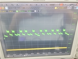
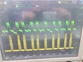
Below Oscilloscope data is same 0 DAC Limit but different current output because of Sync period
Yellow : Laser Red Current(1A/Scale)
Green : Laser Red Voltage(5V/Scale)
*Sync period 30(Laser slightly On)

*Sync period 210(Laser off)
As you said, zener diode shunt circuit for LED_COMMON_ANODE Peak voltage protection should be effective,
but this has not been resolved yet as the cause is a current malfunction due to DAC Limit, not noise.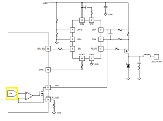
I think this problem is come from LM3409 output generation.
Of course, Coff and Roff degenerate this noise,
But I understood TPS99001's SYNC Pin do same things
and that signal is controlled by DLPC230 Control Program's Pulse control

Sync period 210 cannot fully drive current(left), but sync 30 is better than 210,
So I should set sync period lower because of brightness

Does this mean that this problem is unsolvable using LM3409?

