This thread has been locked.

If you have a related question, please click the "Ask a related question" button in the top right corner. The newly created question will be automatically linked to this question.

DLP4500NIR: Spectral reflectance/transmittance range

Part Number: DLP4500NIR
Other Parts Discussed in Thread: DLP4500

Tool/software:

Hi, I am evaluating the DLP4500NIR DMD for a broadband spectral system and need a clearer picture of the optical losses inside the hermetic package.

From the datasheet I see that:

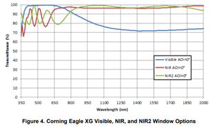
  • The window assembly is specified for high transmittance from ≈ 700 nm to 2000 nm.

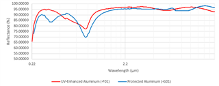
  • The micromirror array is aluminium-coated, so I expect relatively high reflectance well beyond the NIR and for visible wavelengths.


However, my application spans a wider band—400 nm to 2000 nm—including the visible range. Could you please share (or point me to) the following information?

  1. Window Assembly / Package Window

    • Typical or minimum spectral transmittance curve from 400 nm to 2000 nm at normal incidence.

    • Any change in performance at oblique angles (e.g., 24° ± 1°, the nominal micromirror tilt angle).

  2. Micromirror (Aluminium) Array

    • Typical spectral reflectance of the mirror surface over the same 400 nm – 2000 nm range, preferably at both normal incidence and the ±12° operational tilt angles.

    • Confirmation that the mirror coating/process is identical to the one used in the visible-optimized DLP4500, or note any differences specific to the NIR device.

  3. Overall System Throughput

    • If available, a combined throughput or efficiency curve (window × mirror) would be very useful for preliminary SNR calculations.

Even approximate curves or representative data would be extremely helpful! Or recommendation for any other DMD devices that has broad wavelength range from 400nm to 1500nm would be also helpful!

Thank you, 

Suhyun.

  • Hello Suhyun,

    We do not have any DMDs that are designed to span the range from 400nm to 2000nm.  We do not because it s very difficult to design an AR coating over that range.  We offer Visible parts and NIR parts.

    You are correct that the aluminum reflectivity of the mirrors is good across the range you are looking into.

    Please see my responses in blue:

    1. Window Assembly / Package Window

      • Typical or minimum spectral transmittance curve from 400 nm to 2000 nm at normal incidence.  Please see this paper https://www.ti.com/lit/an/dlpa031e/dlpa031e.pdf  [Wavelength Transmittance Considerations for DLP® DMD Window].  This provides the information we have available.

      • Any change in performance at oblique angles (e.g., 24° ± 1°, the nominal micromirror tilt angle).  The paper above provides information on a few select angles, but is limited.

    2. Micromirror (Aluminium) Array

      • Typical spectral reflectance of the mirror surface over the same 400 nm – 2000 nm range, preferably at both normal incidence and the ±12° operational tilt angles.  We do not have this information publicly available.

      • Confirmation that the mirror coating/process is identical to the one used in the visible-optimized DLP4500, or note any differences specific to the NIR device.  There is no difference of the mirrors themselves for NIR devices.

    3. Overall System Throughput

      • If available, a combined throughput or efficiency curve (window × mirror) would be very useful for preliminary SNR calculations.  In the data sheet for visible DMDs there is an estimate based on parameters for a typical projection system.  There are just too many variables to even begin to make an estimate.  An optical model needs to be made of the system in question.

    There is one other very important factor to consider.  The efficiency will be greatly affected by wavelength and diffraction efficiency.  I recommend taking a look at this Matlab model we have available:  https://www.ti.com/tool/download/DMD-DIFFRACTION-EFFICIENCY-CALCULATOR 

    Fizix

  • Dear Fizix,

    Thank you again for your detailed response.

    I just wanted to confirm if I’ve understood things correctly.

    Regarding the window transmittance of the DLP4500NIR, I referred to the application note you shared and extracted the following image from it (attached below).
    However, I am a bit confused — in the plot, which curve corresponds to the DLP4500NIR? Is it the red or the green one?


    In addition, concerning the micromirror reflectance, you mentioned that the DMD mirrors are aluminum-coated and should have relatively high reflectance over a broad spectral range.

    To estimate the reflectance, I looked up typical aluminum coatings on Thorlabs and found the attached plot. In this graph, the red curve shows UV-enhanced aluminum, and the blue curve represents protected aluminum.

    Would it be reasonable to use the blue curve (protected aluminum) as an approximation for the DLP4500NIR micromirror reflectance?


    Any clarification would be greatly appreciated.

    Best,
    Suhyun


  • Hello again Suhyun,

    The first graph applies to the window, which is common to most of our DMDs.  The newer DLP4500NIR DMDs will come with the NIR2 AR coating.

    For the second chart, the blue trace would be a good approximation.

    Fizix

  • Thank you, Fizix.

    I have one last question. I have found that to control DLP4500NIR DMD, we need to purchase DLP4500EVM and switch the DMD.

    However, since the DLP4500 EVM uses DLP4500FQE device and DLP4500NIR DMD comes in CLG(FQD) package, the package type and number of pins are differnt between these two devices.

    So it requires me to make a new flex cable  and also build/source DMD mounting hardware.

    (The DMD mounting can be refered to the application note on "DLP® Series-310 DMD and System Mounting Concepts" for recommended practice for the DMD mounting)

    However, I am not an expert in this H/W systems so I really didn't catch up how I should make a new flex cable and mountings here.  Could you give me some advice?

    Thank you again for your help.

  • Hello Suhyun,

    My colleague is currently out of office and I will be filling in for him on E2E while he is away.

    To proceed, you will need to design a new flex cable and develop custom mounting hardware that accommodates the CLG package. Reviewing the “DLPS Series-310 DMD and System Mounting Concepts" is a great start since it provides best practices for mounting CLG-packaged DMDs, including mechanical design recommendations, alignment considerations, and interface guidelines.

    Since this system is not in your area of expertise, it may be helpful to collaborate with a mechanical engineer or an interconnect provider experienced with high-density interconnects and optical system integration.

    The OMM Tool provides a list of third-party optical module manufacturers who have experience working with DLP® technology. Many of these partners offer custom flex cable design services, DMD-compatible optical engine development, mechanical mount and housing solutions, etc.

    If you’re unsure how to create a new flex cable or mounting solution for the DLP4500NIR (CLG package), the OMM Tool is a great place to identify experienced vendors who may already have compatible designs or can assist with custom work.

    You can access the tool here: DLP Optical Module Manufacturer (OMM) Tool

    Thank you and Best Regards, 

    Tristan Bottone