DLPC7540EVM: Cannot connect to DLP471TEEVM

Part Number: DLPC7540EVM
Other Parts Discussed in Thread: DLP471TE, DLPC7540, DLPC4420, DLPC6540, 4430, DLP650TE, DLP471TEEVM, DLP650TEEVM

Tool/software:

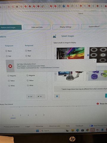
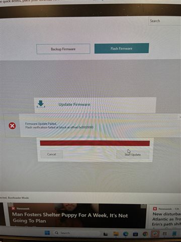
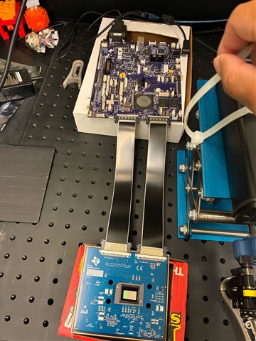
I followed the instructions to connect the device, install the GUI and update the software. The light D6 is always red.

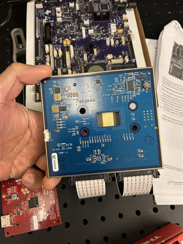
Even if I connect the jumper to J67 on the board, the system will swtich back to Bootloader mode. 

Please advice.

  • Also when I upload the firmware it will fail the first time with error code"Flash verification failed at block at offset 0x00020000"

    But it will succeed the second time. 

    I used the correct 471 firmware got from another thread

  • which driver did you use?  i'm having the same issue

  • I see your other posts, I'm not sure we have the same issue. I can connect to the 7540EVM in GUI and it recongize the main board. My problem is the DMD display board is not recongized. 

  • that may be from the original board I had which was RMA'd  I got a replacement and can connect to the 7540EVM with the GUI just doesnt see the 471

  • Okay then we are on the same page--I tried the correct 471TE firmware too but it still doesn't work.

    From another thread I know that the D6 lit up is potentially due to chip failture(either it is malfunctioning or damaged during operation). So you probably need to replace the 471TEEVM board. 

    I haven't got any answer from any actual technician though maybe there is some fix.

  • i had actually bought a new 471TEEVM just in case and its still has a red comm light.  I think there is something else causing problems

  • Hello Ziqi,

    Welcome to the E2E forum and thank you for your interest in DLP® technology.

     Can you please provide the status of the LEDs on the EVM when you power up the board with SW5 and SW1? D6 is a Red LED, and it should be ON during normal operation. 

    Did you follow the steps in the DLPC7540 EVM User's guide to program the firmware image file for DLP471TE EVM? Did you have the J9 with jumper when programming, and remove it for normal operation?

    Regards,

    Lori 

  • Hi Lori,

    Thank you for your kind reply.

    D6 is red and the other 3LEDs are green.

    When programming, the jumper is moved to J9 and the GUI identified it as Bootloader mode.

    while uploading, it shows error code “Flash verification failed at block at offset 0x00020000" for the first try always, but if try again it says it is successful in GUI.

    After this we cannot operate normally after move the jumper to J67. The D17(LED right next to D6) flashes 3 seconds as the manual says it should do, but we see no logo displayed. This is with the 472TEEVM firmware. 

    if using the correct 471TEEVM firmware, I didn’t even see the 3second flashing.

    The GUI will show the system is in display mode for a seconds and then will jump back to booltloder mode.

    We would really love to have a replacement order for both the 7540EVM and 471EVM board if that is an option.

  • Also you said the D6 is on during normal operation, however it seems to be on no matter where I put the jumper, to J9 or J67, the red D6 LED always lit up.

  • Hi Ziqi,

    Can you please double check if you have the correct power up LED status as following after programming the correcthttps://e2e.ti.com/cfs-file/__key/communityserver-discussions-components-files/94/1731.Flash_5F00_DLPC7540_5F00_DLP471TE_5F00_LED.img successfully?

    1. 12V Power supply connected: no LED ON

    2. SW5 ON: D8 red LED ON, D52 Green LED ON

    3. SW1 ON: D8 Red LED OFF, D5, D7 Green LED ON, D15 Green LED flashing, D6 Red LED ON, D52 keeps ON

    Also, can you see if you can switch the display mode i.g. splash, test pattern?

    Regards,

    Lori 

  • 1 and 2 yes it behaves as you described.

    For 3, if I use the 471 firmware you just provided, the D15 green light is not flashing but stays green. 
    If use the 472 firmware provided on the official website, yes it flashes for 3 seconds, and the system swtiched into display mode, but no TI logi being displayed as it should. And after a few seconds, the GUI loses connection, and then reconnect in Bootload mode. 

    The splash image display, I assume you mean the display splash image in GUI, doesn't work, with the error message "0x2: invalid or unknown message". This is with the 472TE firmware, which is so far the only software can put the device, even for short time, into the display external mode. 

    We also saw the following error message while loading the firmware. If you try again, it will succeed. But first time it shows this every time you upload a new firmware. 

  • Dear Lori,

    Any diagnosis?

  • Hi Ziqi,

    Can you please confirm the DMD you are using? It would be good to provide a picture of the set up you have.

    Also, can you please share the debug log by using a RS232-to-USB cable connect with J102. The debug log is sent through serial port using a baud of 115200. You can use Advance mode in the GUI, in the Connection page, connect the logging Interface with UART and proper port COM. Then power up the EVM, you will see the debug log information in the Debug Log window, and please share the log with a .txt file. 

    Regards,

    Lori 

  • ----------------------------------------
    Debug opened on URT0
    datapath: autolock initialization passed 
    adccontrol: Cfg failed
    digcontrol: powerNormal complete
    datapath: dig, adc, dec powerNormal
    source: SetUserSFGColor = 1
    9
    dispfmt_CalculateDisplayArea:  X, Y, Width, Height = 0, 0, 3840, 2160
    dispfmt:apply_disp: activeSource = 1, dispSrc = 1
    source: SPLASH address:  0x10507764
    source: DisplaySplash size = 3840 x 2160
    Blank screen is set to splash 
    dispfmt_CalculateDisplayArea:  X, Y, Width, Height = 0, 0, 3840, 2160
    dispfmt: minPan, pan, maxPan:0, 0, 0
             data = { 3840, 0, 3840 }
    dispfmt: minScan, scan, maxScan:0, 0, 0
             data = { 2160, 0, 2160 }
    dispfmt_CalculateCroppedArea:  X, Y, Width, Height = 0, 0, 3840, 2160
    dispfmt:apply_disp: activeSource = 2, dispSrc = 2
    
    datapath: Transition to IDLING on Vx1(ITE)
    dispfmt_ConfigManualWarp(): LensCorrection enabled = 0
    dispfmt_ConfigManualWarp: Config warping failed with error code -16
     Actuator EEPROM size - 6 (where 0 = 0.125k,1 = 0.25k,2 = 0.5k,3 = 1k,4 = 2k,5 = 4k,6 = 8k)
    
     [Actuator Type]: 128   [AWC WG Auto-Offset]: 0
    
     Actuator Type: 128   Unipolar: 0
     XPR Param in EEPROM: MAtch Signature
    XPR 4 Way Orientation number: 22
    XPR: Act subframe order: 0 3 1 2
     XPR_4WAY_TIActGetActuatorData(): Read from EEPROM failed
     XPR_4WAY_TIActGetActuatorData(): Read from actuator failed!!! 
    datapathf: XPR_4WAY_Init Failed
    ERROR: Product Configuration Invalid, System Locked 
    ERROR: Product Configuration Failed Cause: Invalid Project used; please check the DMD Timing file 
    illumination: DMD is invalid for this system config error in DMD_Power()
    
    illumination: Can't set up DMD
    sysmon: Fault in illumination transition to operating mode
    sysmon: Sysmon can't transition to operating mode
    illumination: Disabling SSI Illuminators.
    illumination.c : line - 947 : illum_enableIllumination()
    SSI_DRV_Enable() failed
    illumination: API WARNING - SEQ_POWER_DOWN_REFRESH_NOT_USED on Fusion DMD
    sysmon: _sysStandby - Transition to powerStandby
    
    ----------------------------------------
    In Bootloader = v0.12.1 [LLFAULT in app : code = 12]


    We are using  the 471TE. 
    Please see the debug log and image. I do believe everything is setup correctly as the manual indicates. 

  • Hello Ziqi,

    Thank you for providing the information! 

    In the debug log, I see there is product configuration errors which could cause the DMD is invalid and cannot boot up properly. 

    You may want to reprogram the bootloader with JTAG. Please refer to the JTAG bootloader programming guide on the DLPC4420AEVM page of the DLPC4420EVM-SW package. This guide is for DLPC4420/4430, but you can use it as reference for DLPC7540 and need to use the proper DLPC7540 board file and flash image file. You can find the bootloader.bin file in the directory of GUI download, for example, "C:\Users\user_name\AppData\Roaming\Texas Instruments\DLP EVM GUI 3.2.0.7\settings\DLPC6540Project\Inputs\Firmware\bootloader.bin". The bootloader is the same for DLPC6540 and DLPC7540. 

    Meanwhile, can you please provide the picture of the back of the DMD showing the part number?

    Regards,

    Lori 

  • Hello Lori,

    Here's a picture of the back of the DMD. We are trying the boot loader but it doesn't seem to work. 

    At this point, we are really far behind schedule and may want to move on---It will be really nice if you can issue an return/replacement RMA so we can send it back for a tested working set or some professional fix. 


  • Dear Lori,

    In fact we got another set of 7540EVM board and 471EEVM board, and this time we made sure all necessary pocedures are strictly followed, all lights are turned on correctly, and jumper is added at J9 when programming and at J67 while running. we used the 471.img firmware. We saw exactly the same problem as we had before, after updating the firmware, the all system will try to connect to display mode, then disconnect on its own and return to boot loader mode. 

    Also we didn't see at all the D15 LED flashing when use the provided 471 firmware.  It is very strange, as when originally we use the 472 firmware we saw the light flashing. 

    We are told by customer sales team that the 471EEVM actually has the 472 mirror mounted on it, I'm wondering it this is the reason? Which firmware at the end of day should we use for this product? 

  • Hi Lori, 

    As we are following the JTAG Flash Programming Guide, it's mentioned that the Programmer Tool requires a UM232H module. Is it true that we will need to purchase additional parts just to fix this? 
    Because when we run the Flash Programmer program, it is giving the error message that no FTDI is installed. 

  • Dear Lori,

    If we use the 472TEEVM firmware we saw the debug log gives quite different results. Please also take a look.

    ----------------------------------------
    Debug opened on URT0
    sysmon: URT Cmd Handlerfailed to start 
    pca9539: Error - iox failure. APIcc = -7
    
    
    deccontrol: Init failed with Status : -3 
    
    
    deccontrol: Init failed with Status : -3 
    IT6807 - Configuring IT680x... 
    digcontrol: Cfg complete
    IT6807 - Failed in IT680x_Write: IT680x_I2C_DRIVER_ERROR 
    IT6807 - Failed in IT680x_Write: IT680x_I2C_DRIVER_ERROR 
    IT6807 - Failed in IT680x_Write: IT680x_I2C_DRIVER_ERROR 
    IT6807 - Failed in IT680x_Write: IT680x_I2C_DRIVER_ERROR 
    IT68051 - Configuring IT680x... 
    digcontrol: Cfg complete
    IT6807 - Failed in IT680x_Write: IT680x_I2C_DRIVER_ERROR 
    IT6807 - Failed in IT680x_Write: IT680x_I2C_DRIVER_ERROR 
    IT6807 - Failed in IT680x_Write: IT680x_I2C_DRIVER_ERROR 
    IT6807 - Failed in IT680x_Write: IT680x_I2C_DRIVER_ERROR 
    IT68052 - Configuring IT680x... 
    digcontrol: Cfg complete
    IT68052 - Configuring IT680x... 
    digcontrol: Cfg complete
    IT6807 - Failed in IT680x_Write: IT680x_I2C_DRIVER_ERROR 
    IT6807 - Failed in IT680x_Write: IT680x_I2C_DRIVER_ERROR 
    IT6807 - Failed in IT680x_Write: IT680x_I2C_DRIVER_ERROR 
    IT6807 - Failed in IT680x_Write: IT680x_I2C_DRIVER_ERROR 
    digcontrol: Decoder 5 powerStandby complete
    adccontrol: Cfg failed
    adccontrol: ADC_SetDevicePower(FALSE) fail: -5
    datapath: PowerStandby Complete..
    sysmon: DLPA100 not present 
    
    illumination: Starting SSI Initialization...
      Configured SSI Driver Type = 0.
      Configuring sensor failed : -6.
      Initializing WPC configuration...
      SSI initialization failed.
    Sysmon: Transition to normal operating mode
      Initializing WPC Failed: -6
      Initializing WPC calibration data Passed...
      Initializing WPC Brightness Table Failed: 0
    datapath: autolock initialization passed 
    adccontrol: Cfg failed
    digcontrol: powerNormal complete
    datapath: dig, adc, dec powerNormal
    source: SetUserSFGColor = 1
    9
    dispfmt_CalculateDisplayArea:  X, Y, Width, Height = 0, 0, 3840, 2160
    dispfmt:apply_disp: activeSource = 1, dispSrc = 1
    source: SPLASH address:  0x10507764
    source: DisplaySplash size = 3840 x 2160
    Blank screen is set to splash 
    dispfmt_CalculateDisplayArea:  X, Y, Width, Height = 0, 0, 3840, 2160
    dispfmt: minPan, pan, maxPan:0, 0, 0
             data = { 3840, 0, 3840 }
    dispfmt: minScan, scan, maxScan:0, 0, 0
             data = { 2160, 0, 2160 }
    dispfmt_CalculateCroppedArea:  X, Y, Width, Height = 0, 0, 3840, 2160
    dispfmt:apply_disp: activeSource = 2, dispSrc = 2
    
    datapath: Transition to IDLING on Vx1(ITE)
    dispfmt_ConfigManualWarp(): LensCorrection enabled = 0
    dispfmt_ConfigManualWarp: Config warping failed with error code -16
     Actuator EEPROM size - 6 (where 0 = 0.125k,1 = 0.25k,2 = 0.5k,3 = 1k,4 = 2k,5 = 4k,6 = 8k)
    
     [Actuator Type]: 128   [AWC WG Auto-Offset]: 0
    
     Actuator Type: 128   Unipolar: 0
     XPR Param in EEPROM: MAtch Signature
    XPR 4 Way Orientation number: 22
    XPR: Act subframe order: 0 3 1 2
     XPR_4WAY_TIActGetActuatorData(): Read from EEPROM failed
     XPR_4WAY_TIActGetActuatorData(): Read from actuator failed!!! 
    datapathf: XPR_4WAY_Init Failed
    ERROR: Product Configuration Invalid, System Locked 
    ERROR: Product Configuration Failed Cause: Invalid Project used; please check the DMD Timing file 
    illumination: DMD is invalid for this system config error in DMD_Power()
    
    illumination: Can't set up DMD
    sysmon: Fault in illumination transition to operating mode
    sysmon: Sysmon can't transition to operating mode
    illumination: Disabling SSI Illuminators.
    illumination.c : line - 947 : illum_enableIllumination()
    SSI_DRV_Enable() failed
    illumination: API WARNING - SEQ_POWER_DOWN_REFRESH_NOT_USED on Fusion DMD
    sysmon: _sysStandby - Transition to powerStandby
    
    ----------------------------------------
    In Bootloader = v0.12.1 [LLFAULT in app : code = 12]


  • Hi Anderson, 

    You will need the UM232H to reprogram the JTAG. If you have the UM232H connected with the JTAG connector on the formatter board, also make sure you have the correct connections between UM232H and Molex 51021-0600, if you see the FTDI is not found, then double check if you close the GUI, because the GUI could connect with the FTDI and it does not allow you to connect with the programmer tool. 

    Regards,

    Lori 

  • Hello Ziqi,

    The picture you shared for the back of the DMD is not too clear. I saw it is DLP650TEA0FYP instead of DLP471TEA0FYN. Can you please confirm it?

    Each DMD has its own flash image flash to make it work properly. 

    Regards,

    Lori 

  • yes, it is DLP650TEA0FYP.  So that means the firmware is not accurate from the beginning I suppose? We did in fact order the 471TEEVM as per the invoice/receipt

  • Hi Ziqi,

    Yes, you were using the incorrect flash image file to program the board. Please use the DLP650TE image file in the attachment and reprogram it. https://e2e.ti.com/cfs-file/__key/communityserver-discussions-components-files/94/Flash_5F00_DLPC7540_5F00_DLP650TE_5F00_LED_5F00_v5.2.0.A.3.0.img

    If you ordered the DLP471TEEVM,  but you received DLP650TEEVM in wrong order, then you should reach out to your local distributor, whom you purchased the EVM from. They can help you on your wrong order. 

    Regards,

    Lori 

  • Hello, we directly purchased this from TI and the customer support wants us to talk to you as you are the TI engineer. We would prefer to return both the the DLP7540board formatter board as well as the 471TEEVM board(which turns out to be 650) as we no longer trust the reliability of this product. I will forward this to you, the customer support and my colleague for next steps. 

  • Hi Ziqi,

    I'm sorry for your inconvenience. Can I know when did you purchase the EVMs? 

    The EVM has 90 days warranty. Please request for RMA and you can use this thread as proof of RMA authorization. 

    Regards,

    Lori 

  • I've been following this thread after having the same issues, and two DLP471 I ordered from digikey were actually 650 also.  flashed the correct firmware and now get a DLP logo

  • Hi Aaron, 

    Thank you for the feedback and I'm glad the DLP650TEEVM works with the correct image file. 

    I'm not sure how the distributor messed up the DLP471TEEVM and DLP650TEEVM when they shipped out the EVM. If you really need the DLP471TEEVM instead of the DLP650TEEVM, then you should contact Digikey for further customer support. 

    Regards,

    Lori