This thread has been locked.

If you have a related question, please click the "Ask a related question" button in the top right corner. The newly created question will be automatically linked to this question.

Display pattern inversion using internal patterns

Hello,

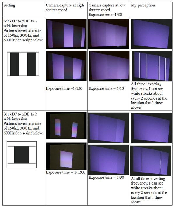
We are testing out internal patterns and our goal is to be able to display two patterns (non-inverted and one inverted) at 300Hz. We are planning to achieve this by first setting the display mode to 1200Hz and then repeating the same patterns 4 times. This should in theory give us 1200/4=300Hz.

We want to make sure that both patterns (non-inverted and inverted) are displayed as expected, we wrote out two test scripts to only display one pattern at a time.

These are the two test scripts we used: (the only difference between these two scripts is the added line to set the inversion mask using 0xD3 sub-address.

Shell script #1:

bus3-i2c 0x1b wb4 0x24 0x00000000
bus3-i2c 0x1b wb4 0x1F 0x0000000A (this set the display mode to 1200Hz)
bus3-i2c 0x1b wb4 0xBE 0x00000040
bus3-i2c 0x1b wb4 0xD8 0x00000001 (repeating this pattern 4 times should simulate 1200/4=300Hz, right?)
bus3-i2c 0x1b wb4 0xD8 0x00000001
bus3-i2c 0x1b wb4 0x29 0x00000000
bus3-i2c 0x1b wb4 0xD2 0x00000000
bus3-i2c 0x1b wb4 0xD2 0x00000031
bus3-i2c 0x1b wb4 0x29 0x00000001

Shell script #2:

bus3-i2c 0x1b wb4 0x24 0x00000000
bus3-i2c 0x1b wb4 0x1F 0x0000000A (this set the display mode to 1200Hz)
bus3-i2c 0x1b wb4 0xBE 0x00000040

bus3-i2c 0x1b wb4 0xD3 0x0000000F (This should invert all 4 repeated patterns, right?)
bus3-i2c 0x1b wb4 0xD8 0x00000001 (repeating this pattern 4 times should simulate 1200/4=300Hz, right?)
bus3-i2c 0x1b wb4 0xD8 0x00000001
bus3-i2c 0x1b wb4 0x29 0x00000000
bus3-i2c 0x1b wb4 0xD2 0x00000000
bus3-i2c 0x1b wb4 0xD2 0x00000031
bus3-i2c 0x1b wb4 0x29 0x00000001

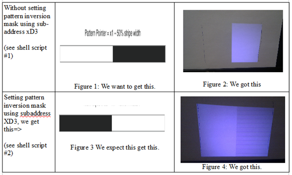
The resulting display is shown in figure 2 and figure 4 in the attached picture.
We have two questions:
(1) Why is the display pattern opposite to what we expect from those listed int he Application Report (DLPA021A-revised October 2011)?
 For example, in figure 1, we expect to see the dark band on the right side but the resulting display show dark band on the left side (figure 2).
(2) Why does the inverted pattern that we see in figure 4 not display the dark band as expected? Why do we only see a slightly darker shade (see figure 4) in the area that is supposed to be much darker?
(3) Did we miss anything in the test script listed above?

Any suggestions would be greatly appreciated!

Thank you
Ku
  • Ku,

    I am very sorry that I missed responding to your message. I need to look into this and understand what is going on. I will respond to you as soon as possible.

    Best regards,

    Pascal

  • Ku,

    I believe that your problem is here:

    bus3-i2c 0x1b wb4 0xD8 0x00000001 (repeating this pattern 4 times should simulate 1200/4=300Hz, right?)
    bus3-i2c 0x1b wb4 0xD8 0x00000001
    bus3-i2c 0x1b wb4 0xD8 0x00000001
    bus3-i2c 0x1b wb4 0xD8 0x00000001

    You are intending to run 4 patterns. This is not the way to set that up. This is just setting up pattern x02 4 times.
    Here is how to set a single pattern repeated 8 times, but inverted the first 4 times:
    bus3-i2c 0x1b wb4 0x24 0x00000000
    bus3-i2c 0x1b wb4 0x1F 0x0000000A (set the display mode to 1200Hz)
    bus3-i2c 0x1b wb4 0xBE 0x00000040
    bus3-i2c 0x1b wb4 0xD3 0x0000000F (this will invert patterns 0x00, 0x01, 0x02, 0x03 - but patterns 0x04, 0x05, 0x06, 0x07 will not be inverted)
    bus3-i2c 0x1b wb4 0xD7 0x00000011
    bus3-i2c 0x1b wb4 0xD8 0x00000011
    bus3-i2c 0x1b wb4 0xD9 0x00000011
    bus3-i2c 0x1b wb4 0xDA 0x00000011
    bus3-i2c 0x1b wb4 0x29 0x00000000
    bus3-i2c 0x1b wb4 0xD2 0x00000000
    bus3-i2c 0x1b wb4 0xD2 0x00000071 (note that now we are running 8 patterns)
    bus3-i2c 0x1b wb4 0x29 0x00000001
    Please try this. It should do what you want.

    Best regards,

    Pascal


  • Hello Pascal,

    Thank you for clarifying the script for internal patterns. I can understand the i2c protocol better now.

    We are trying to study the flicker fusion threshold for human eyes when using structured light patterns. We are hoping that by inverting the patterns at a rate in the range of 100Hz-600Hz, the projected light can appear completely steady to human eyes and that any flickering is not perceived by the human eyes.

    I intentionally 'slow down' the internal patterns to inverting rates of 150Hz, 300Hz, and 600Hz.

    As expected, when I try to invert the patterns at a rate of 150Hz, my eyes can notice the patterns are swithcing

    When I increase the inverting rate to 600Hz, my eyes only see uniform display and can no longer see the patterns that are being used.

    However, there is a very disturbing artifact that I can notice with my eyes at all three frequencies. That is, my eyes can notice vertical streaks appearing on the display at about every 2 seconds interval. The location of the vertical streaks seem to correspond to the boundary location between the ON and OFF light pattern. Please see below for examples. I used Photoshop to edit the display to illustrate what my eyes see. I was not able to capture these streaks with my camera even when I prolong the camera exposure time to 2- 3 seconds.

    Can you offer some explanations why there may be vertical streaks when inverting patterns? For our applications, it is very important that the human eyes perceive only a homogeneous display with no flickering and no streaks.

    I can only hypothesize. But if you can offer any comments, that would be greatly appreciated.

    My current guess is that each subsequent internal pattern is displayed with slightly unequal brightness and my eyes are picking up the subtle difference in signal intensity between each repeating patterns.

    Thank you

    The scripts that were used to generate the above conditions are as followed (similar to what you suggested except I set different instruction for subaddress xD3, xD4)

    Script:

    bus3-i2c 0x1b wb4 0x24 0x00000000

    bus3-i2c 0x1b wb4 0x1F 0x0000000A (set display mode to 1200Hz)

    bus3-i2c 0x1b wb4 0xBE 0x00000040

    if inverting patterns at a rate of 1200/8=150Hz, then I run this

    bus3-i2c 0x1b wb4 0xD3 0x00000000

    bus3-i2c 0x1b wb4 0xD4 0x000000FF

    if inverting patterns at a rate of 1200/4=300Hz, then I run this

    bus3-i2c 0x1b wb4 0xD3 0x0000000F

    bus3-i2c 0x1b wb4 0xD4 0x0000000F

    if inverting patterns at a rate of 1200/2=600Hz, then I run this

    bus3-i2c 0x1b wb4 0xD3 0x00000033

    bus3-i2c 0x1b wb4 0xD4 0x00000033

    bus3-i2c 0x1b wb4 0xD7 0x00000011

    bus3-i2c 0x1b wb4 0xD8 0x00000011

    bus3-i2c 0x1b wb4 0xD9 0x00000011

    bus3-i2c 0x1b wb4 0xDA 0x00000011

    bus3-i2c 0x1b wb4 0xDB 0x00000011

    bus3-i2c 0x1b wb4 0xDC 0x00000011

    bus3-i2c 0x1b wb4 0xDD 0x00000011

    bus3-i2c 0x1b wb4 0xDE 0x00000011

    bus3-i2c 0x1b wb4 0x29 0x00000000

    bus3-i2c 0x1b wb4 0xD2 0x00000000

    bus3-i2c 0x1b wb4 0xD2 0x000000F1 (this is repeating 16 patterns)

    bus3-i2c 0x1b wb4 0x29 0x00000001


    Ku

  • Ku,

    I do believe that I have an explanation for what you are seeing. It is not a "glitch" in the pattern, or the hardware. It is your eyes! Your eyes naturally exhibit quick, jerky movements, one of which is called a saccade. The evolutionary function of this is to "dither" the image on the retina to sharpen and refresh the image processed by the retina/brain. If you stare at something for several seconds, and suppress the saccade, your visual field will become de-sensitised.

    These saccade movements make it look like there are glitches in the patterns which are being projected in rapid sequence. This is entirely an effect of the eyes' motions interacting with the patterns position as seen on the retina.

    Try looking at the patterns and intentionally jerking your eye position. See if you can induce these artifacts.

    Perhaps this is it.

    Best regards,

    Pascal

  • Hi Pascal,

    It is fun that a discussion about the pico projector turns into a discussion about vision and neuroscience.

    Your explanation seems to make sense.  The vertical streaks seem to appear more frequently with more frequent blinking. 

    If I use finer patterns with only 2-4 pixels stripe width and its inversion, instead of observing steaks between patterns boundary, I would notice that the original patterns jump out at me every 2 seconds. It seems like this is due to saccadic masking causing the stopped clock illusion.

    Is it possible to minimize this effect when using the structured light patterns? Our current hypothesis is that we may reduce this stopped-clock illusion if we cycle through as many different patterns as we can in specific sequence. Have you come across possible strategies before?

    If not, does Texas Instrument provide pico projector that provides light patterns outside of visible spectrum?

    Finally, on page 14 of the Pico kit application report, it says that "the internal pattern generator supports up to a 32 frame deep repeating pattern set". However, I am not clear how by only choosing up to 15 choices of patterns allow display of 32 frames of different patterns.

    On page 28 of the chipset programmer's guide, 5 bits (bit 8:4) of of xD2 is allocated to set the number of patterns minus one that will be displayed before pattern sequence repeats. 

    Does this mean if I want to display beyond the 17th pattern using 

    bus3-i2c 0x1b wb4 0xDF 0x00000055
    bus3-i2c 0x1b wb4 0xE0 0x00000055

    bus3-i2c 0x1b wb4 0xE1 0x00000066
    bus3-i2c 0x1b wb4 0xE2 0x00000066

    bus3-i2c 0x1b wb4 0xE3 0x00000077
    bus3-i2c 0x1b wb4 0xE4 0x00000077

    bus3-i2c 0x1b wb4 0xE5 0x00000088
    bus3-i2c 0x1b wb4 0xE6 0x00000088

    I will need to set the maximum number of different patterns possible is by using the i2c command like this:

    bus3-i2c 0x1b wb4 0xD2 0x000001F1 (this means 31+1 patterns, right)

    Thank you

    Best,

    Ku

  • Ku,

    Yes. Fascinating what directions a discussion can go.

    I don't think that increasing the number of distinct patterns helps with the saccadic eye movement induced glitches. Only increasing the repetition rate helps, as far as I'm aware. Certainly, at some frame rate, the rate of angular displacement of the visual field (with respect to the rapidity of the frame rate) becomes too gradual to show the artifacts.

    The "average" pixel value of all of the repeated patterns does remain evident to the eye, though.

    I am not aware of other strategies to diminish this effect. However, you mention of "out of visual band" illumination is pertinent. Using NIR for the pattern illumination is certainly possible. The DLP LightCommander development kit includes a 4th illumination channel, with an LED of around 820nm wavelength. This can certainly be used to avoid having the human subject see the patterns. We provided a demonstration of such an IR 3D capture system recently at Photonics West.

    TI does not make IR enabled pico development kits. However, the recently itroduced DLP LightCrafter industrial pico module and development kit could be modified (by the customer) to utilize NIR out to 950 nm or so. TI does not offer this, but we can refer you to one of our DLP Design Houses, if you are interested in pursuing it.

    About the patterns in the Pico kit - there are 16 patterns, x0 -- xF, and their inversions - making a total of 32 (x20). Your example for the number of patterns register is correct.

    bus3-i2c 0x1b wb4 0xD2 0x000001F1

    x20 - x1 = x1F

    Best regards,

    Pascal

  • Thank you Pascal for all your help and suggestions

    I got a LightCommander to play with now.

    Best,

    Ku

  • Great!

    Pascal