


Hello tech support,
Regarding the input trigger I have gotten feedback regarding the connection:
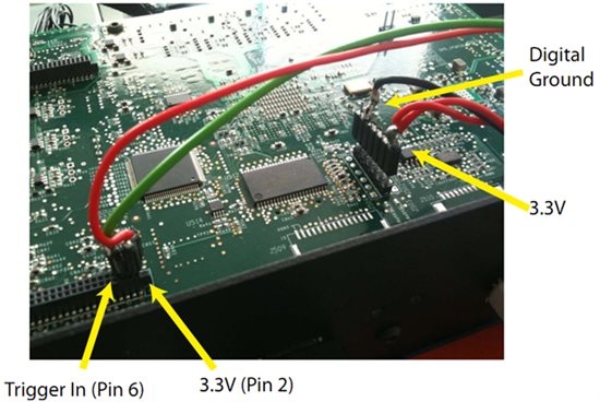
1. Connect VCC_EXP (J505-Pin2) to 3.3V reference
2. Connect an input signal with 3.3V max peak level (Min 0V) Square wave signal/trigger at 60Hz to the EXP_CON_SYNC_IN0 signal (J505-Pin6). Assume the capacitor (C85) is built in the controller board. The peak-to-peak value needs to match the reference voltage input (i.e. 3.3V input at VCC_EXP.) so that you would have an input wave that goes from 0V min to 3.3V max.
3. Using the LOGIC GUI: Set the GUI for Structured Light and static memory. Set the frame rate to 60 frames/sec or just slightly faster than the external trigger frequency, so that I can ensure that I will complete a display cycle before the next trigger is received. Also set GUI time to maximum available "Exposure Time": 16,660 micro-seconds. Set the 3.3V Ext option for the Frame Trigger (Vsync) option and Static image buffer option for Data source.
Though, I came across this specific photo of "tbo"'s trigger connection and found that he has additional connection on J503 supplying 3.3V to pin 1 and grounded pin 6. I looked up on the controller schematics and found that it is connected to the PWM. Mt question he is that what are the J503 pins used for??
tbo's connection photo is attached below:
Regards
Wayne