This thread has been locked.

If you have a related question, please click the "Ask a related question" button in the top right corner. The newly created question will be automatically linked to this question.

DLP LightCommander Specs

Hi

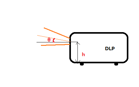
Taking the base of the DLP as 0 degrees, may I know at what angle are the images projected?

Also what is the height of the center of the projected image from the base of the DLP?

Thanks.

Sze Ping

  • Sze Ping,

    I'm not sure that I interpret your questions correctly. If not, please correct me.

    If you consider the plane of the mirror array (base of the DLP - is this what you mean?) as the reference plane, then the active mirrors are tilted either +12 degrees (pixel on), or -12 degrees (pixel off). The "flat" state is not an active or valid operating state. It is a park state, which should be set before power off.

    Considering the "on" mirrors as tilted 12 deg to the plane, then the illumination rays must come from 24 deg off axis, and perpendicular to the tilt axis of the mirrors, in order to reflect the "on" pixel rays perpendicular to the plane of the mirror array.

    I am unsure of what your second question is referring to. If you are asking what is the center of the point of reflection for each mirror, the "height" of the mirror array should be taken as the reference plane.

    Does this answer your questions?

    Best regards,

    Pascal

  • Hi Pascal

    Thank you for your prompt reply. 
    Sorry for my question being unclear,  I've attached a simple illustration of the dimensions I'm looking for.

    Also, may I know the wavelengths of the R,G and B LEDs?

    Thanks.

    Sze Ping 

  • Sze Ping,

    Ah! OK. I will get you something in answer to this shortly.

    Best regards,

    Pascal

  • Sze Ping,

    I am still looking for the LightCommander DMD height and offset.

    However, I do have the wavelengths for the RGB LEDs: RED 623 nm, GREEN 526 nm, BLUE 462

    Here is a link to the manufacturer's page for the RGB LEDs used in the LightCommander: http://www.luminus.com/products/PT-54.html

    B.R.

    Pascal

  • EDIT:

    The dimension given on the slide which was attached here is incorrect. I have gotten the correct value.

    The center of the array to the center of the projection lens is 5.4 mm.

    I apologize for the error.

    Pascal

    Sze Ping,

    Perhaps this slide will help with your question about the DMD offset.

    B. R.

    Pascal

  • Thanks Pascal for the slide. I'll be able to figure out "h" on my own.

    Is "theta" 24 degrees as you explained previously? Or is the plane of the mirror array tilted at a different angle?

  • Sze Ping,

    I do not have a measured value for "h", or I would gladly give it to you.

    No, the "theta" in that diagram is not the same as the illumination angle. I don't know exactly what the "theta" angle is. It would require knowing the distance of the nodal point of your lens from the DMD. The LightCommander is designed for the use of Nikon F-mount lenses. I will try to find the nodal point distance, and calculate the "theta".

    The DMD offset from the center of the lens optical axis has nothing at all to do with the illumination angle required for the DMD which I discussed earlier. That 24 degrees offset is the ray bundle offset required to illuminate the mirrors in order to assure that the "on" mirrors reflect the rays perpendicular to the DMD surface (plane of the mirror array). This allows the projection lens to look straight down on the plane of the DMD.

    On the other hand, the DMD offset shown in the diagram is for the purpose of raising the project image of the DMD above the horizontal, so that the LightCommander can be set on a table, and the image will not be cut off by the table in front of it. This is a common, if not universal, practice in projectors meant for table or ceiling mount. Some customers who are developing non-projector applications with the LightCommander would prefer to have the DMD centered in the lens circle, rather than offset. But, it is designed as it is - in projector style.

    I will try to find a number for the "theta".

    Best regards,

    Pascal

  • Sze Ping,

    I removed the drawing I posted earlier. It had the wrong dimension on it for the DMD offset (center of DMD array to lens axis). I posted a new value of 5.4 mm, but I am still trying to confirm that measurement.

    The angle "theta" will depend on the rear nodal point of whatever lens is used. Unfortunately, Nikon does not publish this value for their lenses, so I don't have an actual number to give you.

    Best regards,

    Pascal

  • Hi Pascal,

    In this case, I'll try to find out theta on my own. 
    I appreciate your  help in finding out the values and thanks for all the information.

    Yours sincerely,
    Sze Ping 

  • Hi again

    I have another question regarding the hardware specs.
    What is the diameter, pitch and length of the screw for the adjustable feet?

    Thanks,

    Sze Ping 

  • Sze Ping,

    The DLP LightCommander feet are (4) 1/4-20 x 1 in. studs.

    Each one is screwed into a molded plastic foot which is 1 in. in diameter, and about 5/16 in. thick.

    Best regards,

    Pascal

  • Thanks!

    Regards
    Sze Ping