In the dlpu04a documents, there is some hint about the exposure time range, eg. for 8 bit depth the exposure time lists is between 8333us to 20ms Or, for 1bit depth the minimum trigger period(exposure time) is 250us.
And in your control software, when i set the exposure time higher than maximum value (e.g. 2sec for 1bit, or 20ms for 2bit), the command did failed. While when the exposure time setting is smaller than the minimum value(but not 0), the command success. My first question is can you tell me what the firmware will do when exposure time setting is smaller than the minimum value?
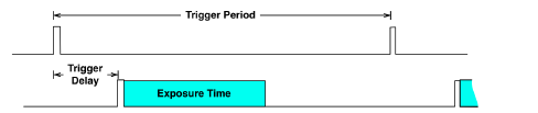
My second question is for the trigger period and trigger delay, is there any limitations on these two values? It seems no matter how long the trigger period i set, the command always succeeded. While the true period is not what i set to. e.g. the trigger period is set with 10 second, while the light crafter does not output the pattern in 10 seconds period.