This thread has been locked.

If you have a related question, please click the "Ask a related question" button in the top right corner. The newly created question will be automatically linked to this question.

Some question about DMD

Other Parts Discussed in Thread: DLP5500, DLPC200

Hi !

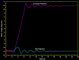
1. the Figure 6 shows that the mirror transition and settle time is 18us, and the time that the tilt angle of the mirror transit from -12 to +12 is about 3us. If I want to change the 3us to 12us ,in other words , to make the red line rise slowly in Figure 6,what should I do ? If there any method? The product that I want to use of TI is DLP5500.          

 Figure 6

2. When the reset signal drive a row of micromirror to change their mechanical position simultaneously, I want to know the time difference between a micromirror and the next one in a row. Is the time difference less then 1ns ?

3. If there same DMDs can be drove to change their mechanical position simultaneously in the diagonal direction like showed in Figure 7 ?

Figure 7

Thank you !

  • Hello Xiaochun,

    Welcome to the DLP section of the TI-E2E Community.  

    • I want to change the 3us to 12us ,in other words , to make the mirror transition time slower what should I do ?

    It is not possible to change the the mirror transition times.  These are governed by the physics of the pixel (i.e. mirror mass/moment of inertia, torsion forces of the hinge and the spring tips).  These cannot be changed in any significant way and have reliable operation of the micromirrors.

    • I want to know the time difference between a micromirror and the next one in a row. Is the time difference less then 1ns ?

    Yes the tranistion of on mirror and the adjacent mirror is less than 1 ns.  The entire row makes the transistion in less than 1 ns.

    • Are there some DMDs can be driven to change their mechanical position simultaneously in the diagonal direction?

    This is not possible in the sense that your are wanting.  It is possible to get a nearly simultaneous transistion of all mirrors on the device.  The DLP550 does this.  All transistions for the DLPC200 controller are "global".  In other words the data is loaded on the entire array an then a global "mirror clocking pulse" is issued that resets all mirrors nearly simultaneously.  The pulse propogates like any signal in a trace across each row. 

    I hope this helps.

    Fizix

  • Hello Fizix,

    Thanks for your answer, it helps a lot.

    1, But I'm confused with the micromirror cross over time that mentioned in the document of DLP® 0.55 XGA Series 450 DMD. It shows us that  the micromirror cross over time normally is 16us,but the max up to 22us. Can you explain why the 1ns leads to the cross over time change form 16us to 22us ?

    2, I would like to know more accurate value of the difference time of the transition between one mirror and the adjacent mirror.You confirmed it was less than 1ns.

    3, In the figure 6, if I can treat the 3us part of the red curve as  straight line ?  If the curve is a  statistical result ,or just the measuring result of one mirror ? The figure quote from "Emerging Digital Micromirror Device (DMD) Applications",Dana Dudley.

    4, The last question , I think there be delay time from RESET signal active to the mirror act. So how long is the delay time ? 

  • Hello Xiaochun,

    Sorry for any confusion.  Let me see if I can clarify.  You asked about the delta in time between one mirror and the next.  This refers to the "micromirror clocking pulse".  That differendce is less than one ns.  The whole row delta is less than one ns since this pulse is applied simultaneously to all micromirrors on a device when "global" mode is used.  It propogates from one side of the DMD to the other in less than 1 ns.

    However, the mirrors themselves mechanically respond to this "clocking pulse" and typically take about 16 us total to move from one side to the other and mechanically settle in the new position.  Variations in production, temperature and other factors can result in a maximum time of 22 us.

    Therefore figure 6 can be interpreted as the statistical result or the response of a "typical" pixel.  There are variations from one pixel to the next in response to the "clocking pulse". 

    For the last question, I am not quite certain how to answer.  Let me say that the "clocking pulse" is 600 - 900 ns long depending on the device.  In figure six the "micromirror clocking pulse" begins when the magenta trace drops (around 2 us on the graph).

    Fizix