This thread has been locked.

If you have a related question, please click the "Ask a related question" button in the top right corner. The newly created question will be automatically linked to this question.

Can't draw lines along the diagonals of the LCr

Other Parts Discussed in Thread: DLPC300

There was a post sometime back by Divya where she described the mirror geometry. In the explanation it seemed that if I ran the projector in its native resolution then the image processing algorithms would be off and there would be a 1 to 1 mapping of pixels from the computer to the LCr.

I understand that the coordinate system on the LCr means that the x pixel spacing is twice the physical distance ans y pixel spacing. By doing the transform, if I created an array in matlab that had a line described by the following coordinates: (1,1); (1,2); (2,1);(2,3);(3,4);(3,5) etc. Then I end up with a line that goes up two and then one over. This pixel mapping in the array when converted into an image should map exactly to the diagonal direction on the mirror array.

Yet when I do this I end up with an image on the lightcrafter that appears as an approximation of "two up and one over". If the coordinates of my image are written in LCr reference why isn't this line travelling along the diagonal axis of the mirror array?

*Some details about my use. I am using the light crafter image to stimulate retinae ( I am a biologist). We minify the image coming out of the projector such that the diamond pixels are now 3um on the diagonal. I can observe the pixel array under my microscope, which is how I know that the line is not what I expect. I generate frames of a movie using the psychophysics toolbox in MATLAB.

I have these questions:

1) Are the algorithims off in HDMI video mode? If no then that explains why the line is not what I expect. If yes, then do I have the coordinate system wrong?

2) What mode allows me to display images on the lightcrafter with the image processing algos completely off? Does this mode (Perhaps pattern display) work the same way as the video mode? For example, is the lightcrafter acting like a second monitor on my video card?

3) Somewhat unrelated to the above but, can I get the output trigger from the LCr on Pattern Display mode? If not then which mode? 

Thanks

Arjun

  • Arjun,

    The pixels in a diamond array (DLP3000) are exactly like those in an orthogonal array - except that the whole array is rotated 45 degrees.

    Orthogonal:

    Diamond:

    Notice that there is no difference in the mirror-to-mirror relationship between the orthogonal and diamond. There is only a difference in the way that we define what is a horizontal row. Notice that each successive row is offset to the right or the left of the rows above and below.

    A horizontal row is made up of the mirrors which touch only at the points, horizontally accross. By inspection of the geometry, you can see that the mirror spacing, center to center, for a horizontal row is (√2). The vertical spacing between rows is (√2)/2.

    You will recall that the DLP3000 has a native resolution of 608x684. However, if you multiply by the factors above, you will see that the aspect ratio is 1.7777 (16:9).

    1) 2) In the LightCrafter, the video enhancement features are off when you set the resolution to native 608x684. If you install the 864x480 EDID, then any accepted resolution other than 608x684 will be re-scaled internally to fit the DLP3000. These resolutions are not pixel perfect - they are rescaled.

    3) You may use the output trigger when in the HDMI streaming mode. First, set the "Pattern Sequence" mode and set up the trigger. Then select "HDMI Video". The receipt of VSYNC each frame will cause a trigger event.


  • Hi Pascal,

    Thanks for getting back to me so quickly. Right I understand that the mirror to mirror relationship isn't different between the orthoganal and the diamond. But, the orthogonal vs diamond coordinate systems means I have to fill pixels in an orthogonal array (such as matlabs) in a way that follows this scheme (x,y): (1,1); (1,2); (2,1);(2,3);(3,4);(3,5)..... These pixels near as I understand correspond to one of your diagonal rows in the diamond configuration.

    this line appears on the orthoganal array as a line that grows by two, then steps over one. Yet when I made this line, sent it to the lightcrafter through the hdmi video cord as the LCr was in HDMI mode (604x684) I didn't fill pixels on the diagonal and instead got what the line I created in the orthogonal array, except distorted because you can't do "grow by two then step one over" on the diamond grid. Seemed to me there was some image processing algorithim still active and still attempting to give me my 'funny' line that I drew to try and fill pixels along your diagonal.

    2) HDMI mode, select 608x684 and then all algos are off? then why was it showing my line as I drew it and not as if I was filling in pixels along the diagonal?

    3) I tried this. Went to Pattern sequence mode. Set the trigger to have no delay, and have a width of a ms, clicked enable and set. Then changed mode to HDMI mode. Got no trigger signals. Am I doing something wrong?

    Arjun

  • Arjun,

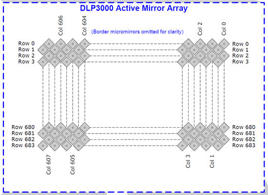
    Please look at the DLP3000 http://www.ti.com/product/dlp3000 data sheet http://www.ti.com/lit/ds/symlink/dlp3000.pdf. Look at page 5. This page has a picture showing the numbering of the columns and rows of the DLP3000.

    For example: if you wanted a 45 degree diagonal line running from the upper right corner, down and to the left (by the picture) you would address (column:row) 0:0 0:1 1:2 1:3 2:4 2:5 3:6 3:7 4:8 4:9 . . . etc. Notice that each column zigzags by one pixel.

    Trigger: What bit depth did you select for your images? The trigger is timed differently according to the bit depth. See the DLPC300 data sheet http://www.ti.com/lit/ds/symlink/dlpc300.pdf. See pages 5-6.

    Please see the DLP® LightCrafter™ Evaluation Module (EVM) User's Guide http://www.ti.com/lit/ug/dlpu006a/dlpu006a.pdf section 4.1. The trigger connector from the LightCrafter System Board is J7, next to the USB connector. Pin 3 is the trigger output. NOTE: the trigger output is an open drain output. That is, it sinks current when it is active, and does not sink current when it is inactive. That means that you can't see this signal on an oscilloscope unless you attach a proper pull-up resistor to pin 1 (Trigger VCC).

    If you are interfacing to a camera, you should refer to Using the DLP® LightCrafter™ to Trigger CCD Cameras from The Imaging Source® http://www.ti.com/lit/wp/dlpa032/dlpa032.pdf. Connections to other cameras will vary, according to their trigger input circuits.

     I hope this helps.


  • Pascal,

    I have a similar problem to consult you. I have a series of binary patterns, each has only one active horizontal line. What I am hoping to do is to find out the correct mirror coordinates for the input line, preferably without scaling. I assumed I can follow the example you gave above -- mapping 0:0 to pixel 0, 1:0 to pixel 1, 0:1 to pixel 2, 1:1 to pixel 3 etc. The problem I am having is that I didn't seem to have a continuous line (I understand it will be jagged), there seemed to be some gap between every two pixels:

    0           2           4

       1          3            5

    (Arjun, sorry to jump into your thread.)

    Thanks,

    Regards, Bing

  • Bing,

    Single row horizontal lines are easy! It is the vertical columns which zig-zag down the array (but they are also easy to specify, they just zig-zag).

    So, for a horizontal line, for example at Row 100:

    (ROW:COL) 100:000, 100:001, 100:002, . . ., 100:607

    A vertical line would look like this (COL 100):

    (ROW:COL) 000:100, 001:100, 002:100, . . ., 683:100

    See if that will do what you want.

  • Pascal, thanks for such prompt response! It seems with what you suggested, I will have only 608 active pixels on that line though... What I am hoping is to map my input pattern (assume the line have 854 pixels) and the DMD mirror coordinates, (preferably without scaling...). In this case it seems to me from the diagram above, the line will be zig-zag?

    Thanks again. 


  • Bing,

    As you can see from the physical arrangement of the mirrors (the diagram you mention, above) there is no way to do 854 pixels across. You can do two successive rows, though, which would result in 1216 pixels across, with the small zig-zag.

    Scaling works by mapping an arbitrary resolution (say, 854x480) to the physical array structure. With what you are attempting, it is best to work directly with the physical array structure, which is what I have illustrated above.

  • Pascal,

    I think I will use the middle 864 pixels of two rows.

    Thanks a lot!

  • Hi Bing,

    I've written some handy code that should let you remap rectilinear pixels (regular monitor ones) to diamond ones message me if you'd like it. Perhaps it'll help

    A

  • Arjun, thanks a lot! I sure can use it.

    Regards, Bing