This thread has been locked.

If you have a related question, please click the "Ask a related question" button in the top right corner. The newly created question will be automatically linked to this question.

Problems triggering a CCD camera from the Imaging Source

Other Parts Discussed in Thread: TXS0101

Hi,

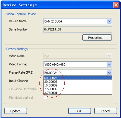
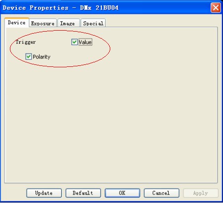
I'm trying to trigger a CCD camera(DMK 21BU04.H).

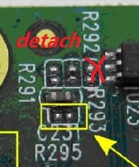
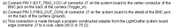
1.Trigger Connection setup, see:

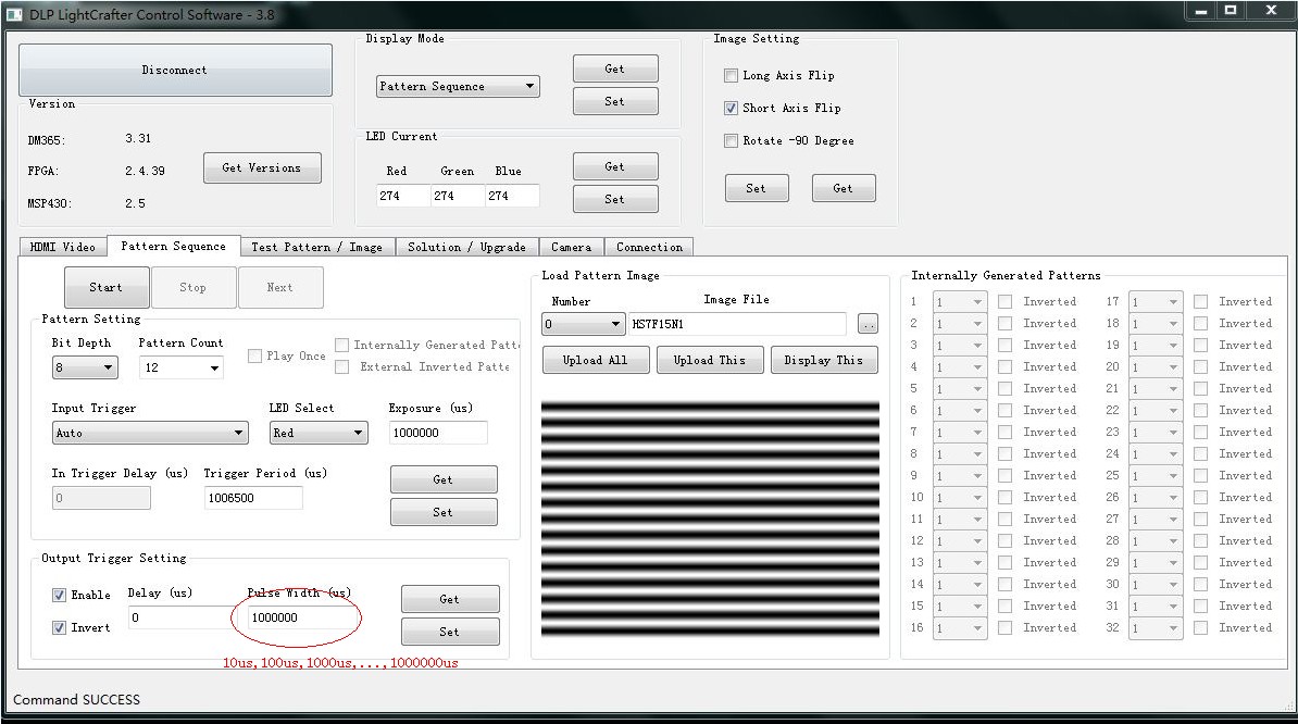
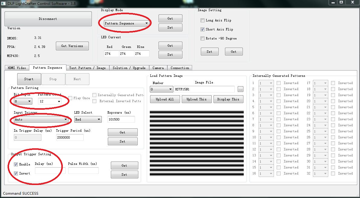
2.DLP LightCrafter Control Software setup,see:

3.Question: The LightCrafter can't output the trigger signal to trigger the camera properly. How to do it?

  • Hello Yin Lou,

    #3. Are you not seeing the trigger pulse at all? Please set non-zero pulse width and verify if it helps. For example- Set Output Trigger Pulse Width to 10uSec.

    Regards,

    Sanjeev


  • Hello Sanjeev,

    Thank you for your reply. I set the trigger pulse(10us,100us,1000us,...,1000000us), but it can't  work.

    #1.This is the LightCrafter's settings. As follow:

    #2.The camera's settings:

    (1)frames rate: 60.00024

    (2) Device trigger : value and polarity

    (3) Exposure :

    (4) Special:

    #3. The trigger supply (PIN 1 of J7) is 3.3V. Is the voltage(3.3V) lower? I did a experiment-----supply a 5V power for camera, it can work, so I infer that  the trigger supply of the LightCrafter is lower. If my deduction is right, how to enhance the trigger supply?

    Regards,

    Lou Jin

  • Hello Lou Jin,

    #1. OK.

    #2. (3) Exposure picture - You may want to disable Auto functionality. By enabling this you end up reading the modified pixel data on the camera as it starts dynamically adjusting the gain of image.

    #3. For this you need modification on the board. Refer to this thread http://e2e.ti.com/support/dlp__mems_micro-electro-mechanical_systems/f/850/p/260558/913724.aspx#913724 here it is discribed on how to get different voltages apart from 3.3V for external camera trigger.

    Let me know if there any question I can help you with.

    Regards,

    Sanjeev

  • Hi Sanjeev,

    I really  appreciate your help. And I refered to the thread above. But I understand a little.

    # 1. How to remove R292 on the board? I do this as follow:

    It is detached from the system board.

    # 2. How to  install 0Ohm at R291. I use a cable to connect two pin on R291. See :

    # 3. Above all , right ? If not, what's right?

    # 4. I have a idea that I make a voltage  amplifier, and place it between the camera and J7. Is it available?

    Regards,

    Lou Jin

  • Hello Lou Jin,

    #2 instead of connecting cable you could have used the same 0Ohm resistor you removed from R292.

    #3. Your changes look proper to me.

    Before going to option #4 I would suggest to test just with #1 and #2 changes.

    Regards,

    Sanjeev


  • Hi Sanjeev,

    I still have some questions. Last night I did my experiment. I found no signal between Pin 1 and Pin 3. No signal! But Pin 2 and Pin 4 is 3.3 Voltage. I have no head.

    DLP LightCrafter Control SoftWare's settings :

    (if the settings is right)

    #1. Before installing 0 ohm resistor at R295, the result of testing Pin 1 and Pin 3 is no signal. There is a 3.3V between Pin 2(Pin3) and Pin 4. And I do nothing for setting the DLP LightCrafter Control SoftWare or I don't open it, there is still a 3.3V between Pin 2(Pin3) and Pin 4. Why?

    By the way, I can't  installed a 0 ohm resistor at R295. The system board is elaborate, and I'm  afraid to spoil the one.

    #2. Refer to this thread http://e2e.ti.com/support/dlp__mems_micro-electro-mechanical_systems/f/850/p/263006/921546.aspx#921546, here is Wang zhen's questions. His and mine are the same. After installing 0 ohm resistor at R295,  the condition isn't changed.

    #3. Would you use some pictures——how to install 0 ohm resistor at R295 and remove R292 on  the system board—— to explain my puzzled?

    Regards,

    Lou Jin


  • Hello Lou Jin,

    #1. Refer to the schematics the Pin#2 of J7 is Trigger I/P and Pin#3 of J7 is Trigger O/P.

    Both Trigger I/P and Trigger O/P signals are connected to bi-direction voltage translators U20 & U23 device TXS0101. By referring to the http://www.ti.com/lit/ds/symlink/txs0101.pdf device spec you will find that the  Port-B signal (to which trigger i/p or trigger o/p signal connected) has a internal 10K pull to VCCB which is 3.3V.

    So, if you measure the voltage b/w Pin2 or Pin3 to Pin 4 of J7 connector you will find it is 3.3V.

    Without R295 installed it is not possible to driver camera having opto-couple trigger input signal. You can take it to board shop to get the modification done.

    #2. Please refer to  http://e2e.ti.com/support/dlp__mems_micro-electro-mechanical_systems/f/850/p/263006/921546.aspx#921546 I have answered there.

    #3. At don't have any pictures to share with you. You can take it to a local PCB board shop and ask them to do the modification they would help.

    Regards,

    Sanjeev


  • Hello Sanjeev,

    Recently, I'm busy doing something else. Last yesterday, I took it to a PCB board shop. And they used a cable instead of the 0 ohm resistor. They didn't install the cable at R295(two red points), but see figure(two red circles):

    # 1. Is this logical?

    # 2. I test its voltage, if other settings have done, and the result is 3.3V, 0V, -3.3V. They are volatile. I deduce that above the way  is right. Your outlook?

    Regards,

    Lou Jin

  • Hello Lou Jin,

    Looks OK to me as well.

    Regards,

    Sanjeev

  • Hello Sanjeev,

    Thank you very much for your help all the time. My problems have been done. Thank you again!

    Second, I want to know something about DLP® LightCrafter™ 4500,but I have nothing on it. Could you provide me with its user‘s guide?

    Regards,

    Lou Jin

  • Hello Jin,

    You are welcome.

    The DLPLightCrafter 4500 user guide is available when we launch the kit. Please hold on until the announcement of the kit.

    Regards,

    Sanjeev

  • Sanjeev,

    Sorry to reopen this old thread... since I need to do the same thing, I just want to clarify it a bit before I proceed.

    From the discussions between you and Lou Jin, there are two ways to generate 5V trigger output:

    1) Putting jumpers between R291 and R295; or

    2) Directly connecting J7 Vcc pin to Pin 6 of U23?

    Could you please confirm?

    BTW on my board, R291,R292 and R293 all seem to be open?

  • Bing,

    The trig_out_con signal on pin 3 of J7 is an open drain connection. That is, it cannot source current, but it can sink current. The correct way to create a 5V trigger is to place zero-ohm jumpers in place of R295 and R291. R292 and R293 should remain open (no zero-ohm jumper). This will place 5V on ext_trig_VCC, pin 1 of J7. Then, to your camera, connect pin 1 of J7 to the trigger input pin, and connect pin 3 of J7 to the camera trigger ground. The ground pins 4, 5, and 6 of J7 should not be connected to the camera.

    Do not connect J7 Vcc pin to pin 6 of U23, except by inserting the zero ohm jumper R295.

  • Thanks a lot for the clarification.