We have recently purchased a new PICO V2 development kit.
We are looking for technical documentation that describes how to use it.
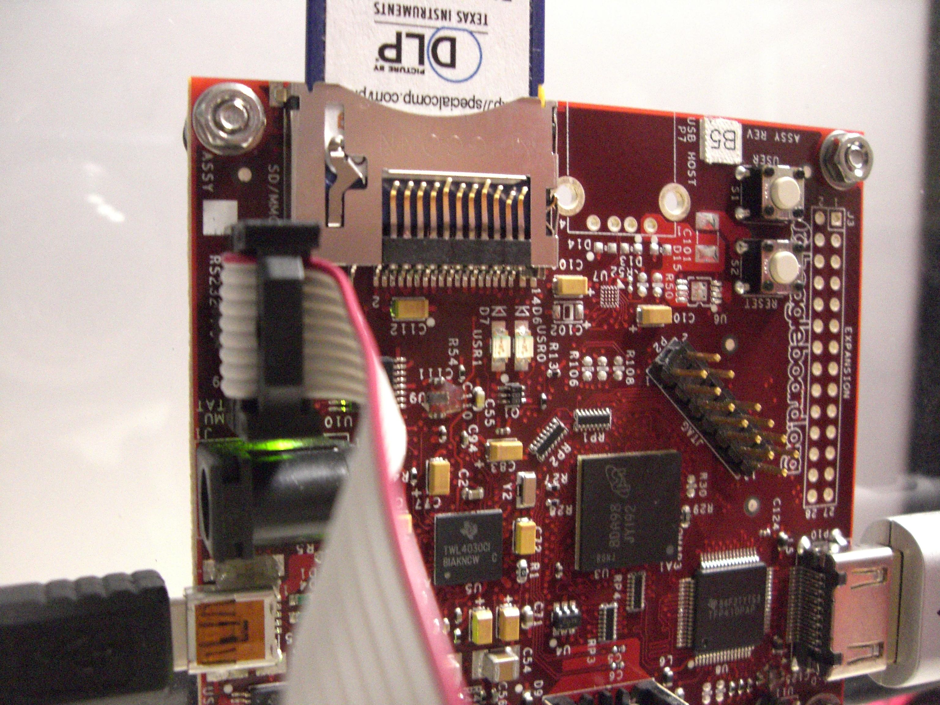
- there is a 14-pin connector
- there is a 25-pin connector
As far as we know, all the PICO documents refer to the original PICO (V1).
We have been told that the new PICO V2 supports
- synchronization with an external camera.
This would enable us to integrate exactly one frame of PICO video
and that would enable use in precision structured light applications.
- I2C interface, but not through the hdmi-C (non-standard) connector.
- run the PICO directly with PC video.
- possibly some new commands / capabilities.
Does TI have any how/to documentation covering the new capabilities?
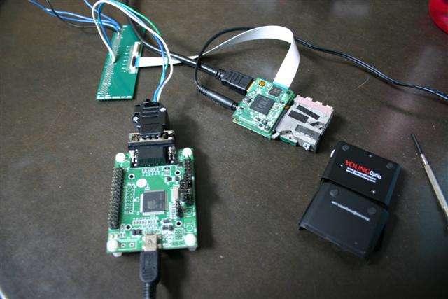
The old PICO (V1) came with a special video cable that allowed connection
to the Beagle Board which supplied the I2C. Can that cable be utilized with
DVI-D video and no I2C (as from a PC), or is its use dangerous to a PICO (V2)?