This thread has been locked.

If you have a related question, please click the "Ask a related question" button in the top right corner. The newly created question will be automatically linked to this question.

Seeking DLPC300 i2c response

Other Parts Discussed in Thread: DLPC300

Hello:

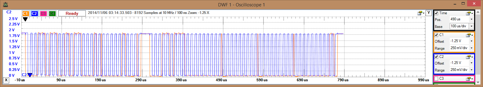
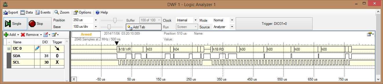
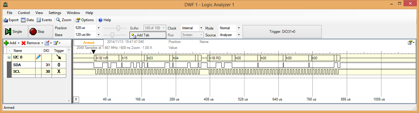
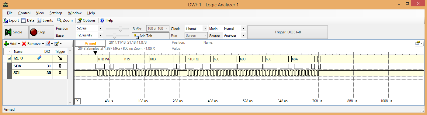
I'm having trouble getting my DLPC300 controller to respond over i2c.  If I send a read message within the 100ms or so of deasserting the RESET line, I get a response from the device--though it's always zeroes.  If I wait the 100ms that TI recommends for the device to go through powerup, the device does not ACK any of my i2c messages.

What are some general strategies and/or gotchas I should be using or checking when trying to diagnose this problem?

  • Hello Geoffrey,

    Please look at the DLPC300 controller datasheet http://www.ti.com/lit/ds/symlink/dlpc300.pdf Powerup initialization sequence section & Figure 18, Initialization Timeline. This will give idea on when to send first command.

    Apart from this, if there is basic, noise issue or mistake in i2c communicaton protocol it may not work.

    Try reducing the I2C_CLK to say 100KHz and test. 

    Regards,
    Sanjeev

  • Sanjeev,

    Thanks for the response!

    I tried lowering the bus speed to 100 kHz as suggested, but this didn't solve the problem.  Eventually I was able to trace the problem of the strange logic level to an issue with my FPGA, and fixed the issue there.
    Attached you will find screenshots from my oscilloscope and logic analyzer.  I'm attempting to read 4 bytes from the DLPC status register 0x03.  I have the i2c slave address select line tied low, and I can see that the DLPC is correctly acknowledging i2c traffic addressed to it.
    The logic levels all look good, there's no ringing going on in any of my transmission lines, and the DLPC's INIT_DONE line pulses as expected long before I attempt any kind of i2c operation, and yet no matter what address I target, I always get zeroes back from the DLPC.
    Any thoughts on what I should try next?  I can probe most of the pins on the DLPC, they are broken out to various test points.
    Cheers
  • I forgot to add these attachments:

  • Hi Geoffrey,

    I wanted to let you know we will have some additional feedback to you early this week.

    Thanks,

    Clinton

  • Hello Geoffrey,

    Couple of inputs for you to try, please look at section 1.1 I2C interface, especially at the 1.1.1.5 and 1.1.1.6 for Read and Write protocol.

    First, since, I2C_ADDR_SEL is LOW, the DLPC300 7-bit address therefore is 0x1B, so for write and transaction to the device the address would be (0x1B << 1) | 0x01 (for read) and (0x1B << 1) | 0x00 (for write), in short the device address would look like 0x37 and 0x36 respectively.

    For example, to read the status register the protocol should be as follows -

    0x36 <register-address-> <number-of-bytes-to-read>

    0x37 <read-data-bytes>

    So, your command bytes must be sent as 

    0x36 0x03 0x04 //Issue command to read status register

    0x37 0xXX 0xXX 0xXX 0xXX   //read number of bytes 

    Regards,

    Sanjeev

  • Hey Sanjeev,

    Once again, thanks for the assistance.

    We have in fact been sending those commands.  The logic analyzer represents the read and write as 1b WT (36) and 1b RD (37).  We also get ack bits from the dmd.  The issue is that our reads are all returning zeros.

    Cheers

  • Hello Geoffrey,

    My suggestion would be to probe for INIT_DONE signal DLPC300 I/O #C9 to have proper transition as follows - 

    1. After RESET, the I/O line should go HIGH, 

    2. It must go LOW to show the initialization completion. 

    3. To be safer side, check if there is a error condition generate via 3us pulse generated.

    Please also confirm if it is your custom board or your testing it on LightCrafter Kit.

    Regards,
    Sanjeev

  • Hey hey,

    Yep, we actually are able to scope INIT_DONE.  We see it go high as soon as we deassert RESET_N, and then a little while later it does go low as expected.  We wait for this event before trying to send i2c.  After we enter this state, we watch the INIT_DONE line for a pulse, which would indicate some kind of problem in the DLPC, and do not observe this.

    We are using a custom board currently.  I can confirm that we have the latest DLPC300 firmware as provided by the TI website.
  • Hello Geoffrey,

    Since everything looked proper as far as physical interface goes, i had to revisit the protocol implementation.

    I got the problem, we missed something critical in the Programmer's Guide documentation, that led to the not working.

    For I2C Read Operation, we must include additional byte at the beginning READ REGISTER SELECT - 0x15 along the register address.

    So do as follows - 

    0x36 0x15 <register_address> <number_of_bytes>

    For example - To read status,

    0x36 0x15 0x03 0x04

    then read the status

    0x037 0xXX 0xXX 0xXX 0xXX

    Thank you for bringing this into the forum, we will update the Programmer's Guide.

    Let us know if you still face any problem.

    Regards,
    Sanjeev

  • Hey Sanjeev,

    That's still not working for us. Here's an image of the new trace:

  • Hello Geoffrey,

    Okay,

    Try below additional options 

    Option 1.

    Don't include number of bytes,

    0x36 0x15 0x03 0x04

    then read

    0x37 0xXX 0xXX 0xXX 0xXX

    Option 2.

    Don't include number of bytes,

    0x36 0x15 0x03 0x04

    //add 10ms delay

    0x37 0xXX 0xXX 0xXX 0xXX

    Option 3.

    0x36 0x15 0x03 0x04

    //add 10ms delay

    0x37 0xXX 0xXX 0xXX 0xXX

    I think Option #1 or #2 should work, let me know.

    Regards,

    Sanjeev

  • Hey Sanjeev,


    Option #1 worked.  I was able to read an address with a well known value.  Here's a trace.

    Attached 

    Now, I tried an i2c write to address 0x30, which is listed as a debug register, and I'm not getting back what I expected.  Here's the sequence I'm using:
    0x36 0x15 0x30 1
    0x37 0x15 0x30
    0x36 XXX XXX XXX XXX
    I think the write is wrong.  Any tips?
  • Hello Geoffrey,

    Good.

    Can you please re-attach the trace? we are not able see the trace, also for others who read this thread it will be very helpful.

    Write protocol also need correction. 

    <I2C_device_address> <register> <four_bytes_of_data>

    0x36 <register_address> <data_byte_3> <data_byte_2> <data_byte_1> <data_byte_0>

    So, the register 0x30 is general purpose read/write register of size 16 bits but the protocol accepts 4 bytes always for data, so you must append MSB bytes with 0x00

    0x36 0x30 0x00 0x00 0xXX 0xXX  // 0xXX are the  actual bytes to write

    Example - 0x36 0x30 0x00 0x00 0xAA 0x55  // will store 0xAA55 in the register 0x30

    Regards,

    Sanjeev

  • Hi Geoffrey,

    Can we get a better understanding of the I2C commands you were issuing to the DLPC300 when you were having this problem originally? Looking at the DLPC300 programmer's guide, the procedure shown represents the sequence of I2C commands that ultimately resolved your issue.

    Thanks,

    Clinton