Hi:
Could anyone help me to check if my solution is right or wrong? I have realized that I should modify the system circuit board to trigger a camera! There are two solution below:
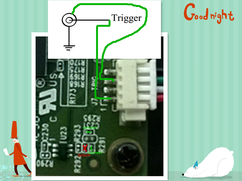
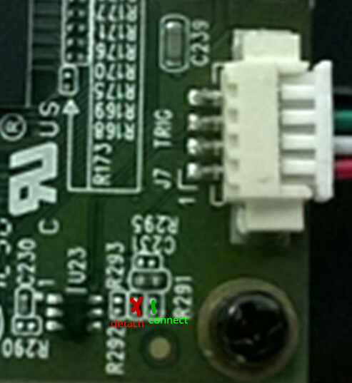
1.detach the R292 and weld a 0 ohm resistor to R291 as the picture below:
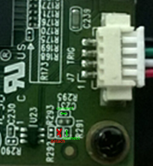
2,detach the R292,weld a 0 ohm resistor to R291 and R295 as the picture below:
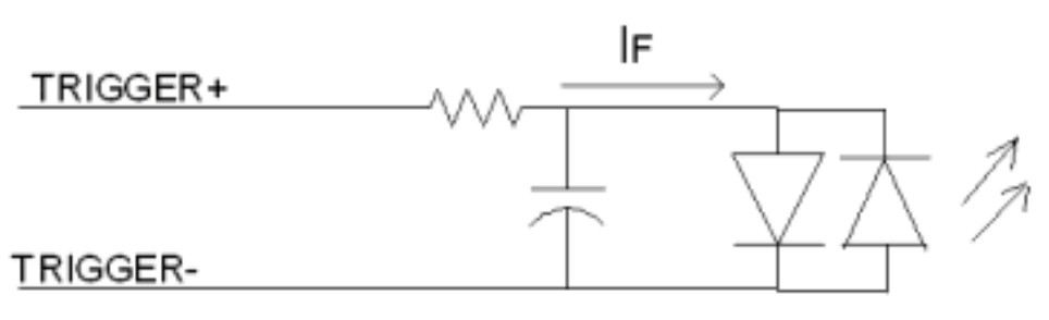
the following picture is the camera' trigger circuit pictrue:
So I think the correct solution is the picture below:

Could anyone tell me which solution is right? if both solution are wrong,how should I do?
Thanks a lot !!!