Dear Sanjeev
Thank you for telling me the information. I have another question about the "3D_Scanner_LCr4500_PGcam.exe".
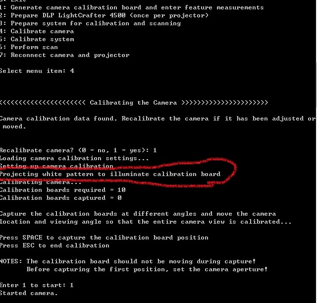
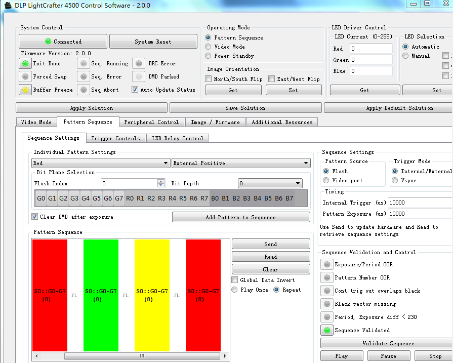
In the step 1-3, the software can success to work.
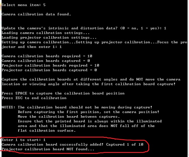
In the step 4-6,The projector can't run correctly. But Camera can capture image.
There are two situations.
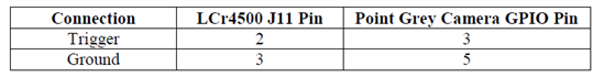
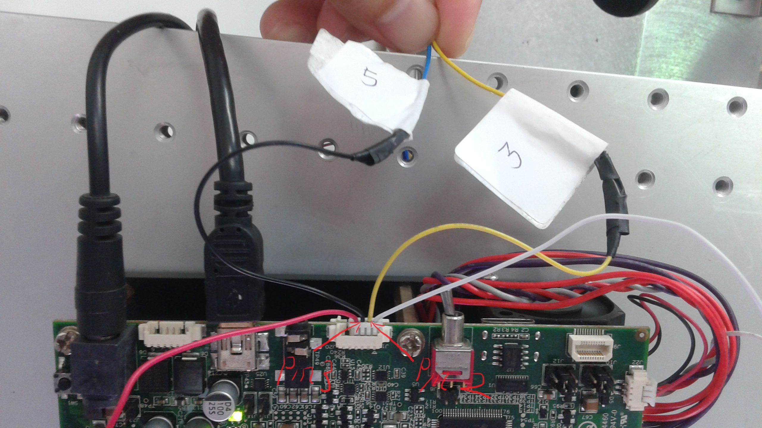
First situation, We use trigger out1 (pin 2) and ground (pin 3). The DLP at step4-6 can't project any patterns.
Second situation, We use trigger out2 (pin 5) and ground (pin 6). The DLP at step4-6 just can project one pattern at each step.
How can I fix the problem? Thank you very much.
Best regards,
Athena.