This thread has been locked.

If you have a related question, please click the "Ask a related question" button in the top right corner. The newly created question will be automatically linked to this question.

DLPC350 Trigger mode0

Guru 10570 points
Other Parts Discussed in Thread: DLPC350

Hello,

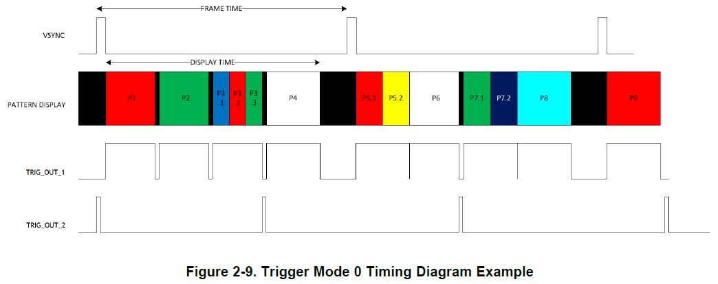
I have a question about the Trigger mode 0 in below figure.

I can not understand the meaning of P3.1, P3.2, P3.3.
In pattern sequence mode(I2C:0x69=1), I think LED color is decided as one color by each pattern.
Can you give me some additional advise about this situation?

When I use DLPC350 as pattern sequence mode(I2C:0x69=1), can I change the FRAME TIME period dinamically?
Because I would like to change display timing.

Best regards, RY

  • I cann't understand the meaning of p3.1 p3.2 p3.3, either.
  • Thanks, user3828459.

    To TIer, do you have any information?

    Best regards, RY

  • Hello RY and user,

    First, P3.1, P3.2, P3.3 refer to pattern LUT entries which have the "Trigger Out 1 will continue to be high" set. This is referred to as "Share exposure time with prev pattern" in the GUI. This setting also causes the patterns to share the exposure time set for the sequence. Please reference bit 2 of byte 2 in Table 2-68 "Pattern Display LUT Data - Pattern Definition Command" in the DLPC350 Programmer's Guide for more information. In the figure you posted above, you can also note that P5.1, P5.2 , P7.1, and P7.2 also use this same setting.

    Unfortunately the VSYNC frame time cannot be modified dynamically. The DLPC350's video port only locks to very stable video frame rates and takes several frames before it locks to the signal.

    Please let me know if either of the answers are unclear.

    Best regards,
    Blair
  • Blair-san,
    Thanks for your advise.
    May I ask some additional questions?

    - Can you clarify the time needed to lock video frame?
    Or, are there any method to know if video frame is locked or not?

    - By trigger mode0 in Figure 2-9, I understand that the pattern and color can be changed in each frame. Is that right ?

    Best regards, RY
  • - Can you clarify the time needed to lock video frame?
    Or, are there any method to know if video frame is locked or not?

    [Sanjeev]
    From DLPC350 F/W v2.0 onward we have introduced new status command to query signal lock status, you can look at Section 2.1.5 Input Video Signal Detection Status in Programmer's Guide. Also please note that you must do the setup in Video Display Mode. Once done, enter Pattern Display Mode with source set to RGB port. In Pattern Display Mode, it expected that the incoming video source is stable, and there are not missing SYNCs in between.

    For detecting a video source or lock to video source, it will take several VSYNCs to detect something like 10-15 VYSNCs periods.

    In the next upcoming releasing, we are planning to keep video frame auto-lock feature enabled in Video Display Mode only, in the Pattern Display Mode it is anyway not having relevance.

    So expected use case - Generate Video Source->Set DLPC350 in Video Display Mode -> Read and ensure source is locked -> Enter Pattern Display Mode with pattern source set to Video Port.

    - By trigger mode0 in Figure 2-9, I understand that the pattern and color can be changed in each frame. Is that right ?
    [Sanjeev] Yes. Also please note, you must set the sum of pattern display period < actual incoming VSYNC period. Anything bigger result in DLPC350 missing VYSNCs and unexpected pattern display behavior.

    Regards,
    Sanjeev