This thread has been locked.

If you have a related question, please click the "Ask a related question" button in the top right corner. The newly created question will be automatically linked to this question.

I2C Interface to DLPC350

Other Parts Discussed in Thread: DLPC350

Hello,

Hopefully someone might be able to point me in the right direction..

I have a custom board with a DLPC350 controller that I'd like to program the firmware via I2C. I was able to use urJTAG in Linux to program the bootloader segment of the flash using the instructions at http://unaligned.org/dlpc350/ ...

With the bootloader programmed, I cannot read data from the registers. I've gone over the I2C read procedure a couple of times.

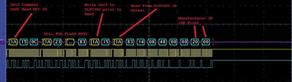
Example, My I2C data for a Read Manufacturer ID "S 0x1A(W) 0x95 0x0C P S 0x1A(W) 0x15 P S 0x1A(R)" After this I read and I get "0xA3 0x14 0x08 0x48". I always get that same pattern, no matter which register I try to read. Based on the Programmer's Guide I expect to see a 0x01 or 0x00 as the first byte from the DLPC350.

Any thoughts, suggestions?

  • Hi Mark,

    Have you successfully downloaded a new firmware image into flash memory over I2C on the LightCrafter4500? This will help determine if you have a hardware issue on your custom board.

    Thanks,
    Clinton
  • Hello Mark,

    We have identified few gaps in the Programmer's Guide documentation.

    Currently the programmer's guide have A) Set of commands when the Bootloader application running B) Set of commands when the Main application is running. Since these two are two different applications we want to divide them in two different sections. The only common commands b/w (A) and (B) is Enter/Exit Program Mode I2C:0x30.

    There is slight change in the WRITE part of the protocol when (A) is running. Don't add 0x80 to the Read Control register 0x15. Could you send just 0x15 instead of 0x95? Let us know if you are now able to read the Manufacturer's ID properly.

    Regards,
    Sanjeev
  • Sanjeev,

    After a bit of trial and error I was able to read the Manufacturer ID and Device ID using the Lightcrafter 4500 via the I2C bus. There are quite a few differences between the programmer's guide and the actual function of the DLPC350 in the programming mode.

    1) As you mention in your post above the 0x80 WRITE bit is not used.
    2) The READ transaction sequence does not use the status bytes (step 5 in the I2C Read Transaction Sequence)
    3) The Programmer's Guide doesn't mention the values returned from DLPC350.  The Manufacturer ID and Device ID are the 7th and 8th bytes read after issuing the 0x15 read command. (see the images below)  This should be noted in the guide.

    A couple of additional questions:

    1) What are the first six bytes returned after the 0x15 read command? They seem to be constant.
    2) Where will the 4-byte checksum be returned? (I can probably figure that out, but I'd like confirmation)

  • Hello Mark,

    We will document  and update the response bytes status - 

    1.

    BYTE[0] = Read Status byte, refer to Table 2-6. Read Status Command 

    BYTE[1] = Boot Loader Application version #

    BYTE[2] = Reserved 0x08

    BYTE[3] = Reserved 0x48

    BYTE[4] = Reserved 0x00

    BYTE[5] = Reserved 0x00

    2.

    Flash Checksum returned from BYTE[6] onwards 

    BYTE[6] = LSB

    BYTE[7] = LSB +1

    BYTE[8] = LSB + 2

    BYTE[9] = LSB + 3

    Regards,
    Sanjeev