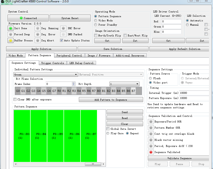
I want to use USB port configuration dlpc350, I used ARM 7 design, which does not install the system, it can not use API. I want your help: how to use USB arranged dlpc350 communication? Do not use the API

-
Ask a related question
What is a related question?A related question is a question created from another question. When the related question is created, it will be automatically linked to the original question.