This thread has been locked.

If you have a related question, please click the "Ask a related question" button in the top right corner. The newly created question will be automatically linked to this question.

LightCrafter 4500, LEDs low intensity and out of sync with splash screen

I was using the LightCrafter 4500 GUI (ver 2.0) to work with the LightCrafter 4500 (ver 1.1 firmware). I was setting the LED current manually while in Video Mode and using the spectroradiometer to measure the light output from each LED independently. Then, unrelated to a command given in the GUI and/or handling the device physically, the LEDs turned off. I have toggled the power supply and unplugged the USB just trying to get the splash screen back. When first powering, the LEDs give a short but bright flash like it's going to turn on correctly, but then the LEDs decrease to a very small percentage of their maximum (<1% is my educated guess). Holding the LightCrafter up to my eye and looking directly into the projector optic, I can see the splash screen present on the mirror and the extremely dim RGB LEDs out of synchronization with the RGB frame of the splash. 

LED D4 blinks green and D7 is constant green. I have upgraded the firmware to version 2.0 in an attempt to fix it, but without success. The LightCrafter 4500 GUI still recognizes the HID as being present (in Video Mode "Init Done" is green, "Seq Running" is green, "Buffer Freeze" is yellow). System Reset does reset the device (loss and subsequent reconnection of USB), but it does not fix the problem. Switching from Video Mode to Pattern Mode keeps the splash screen present on the mirror, but turns off the LEDs completely. In "Video Mode" I can change to an "Internal Test Pattern" and load a checkboard...DLP Mirror updates to checkerboard, however the LEDs, again, flash at low intensity not in sync with the RGB frame.

I am using the 12V, 5A power supply recommended and linked to Digikey from the TI website for the LightCrafter 4500. I see that, according to the manual, a 5A power supply is underrated. I also see in other threads people having measured 5.5A continuous during a full intensity white Pattern Mode presentation. I was only using Video Mode when this happened.

Even though the LightCrafter shouldn't have taxed the power supply in the mode I was using it, the power supply is the only thing I can think of...is there a possibility of damaging a buck/boost circuit by underpowering it (I don't think so, but just asking the question)? I know the LEDs are not burned out as they do flash as previously described. Is there a different possible reason/explanation for this behavior?

I have a 12V 7A power supply on order, but it won't arrive for a few days so I can't troubleshoot further until then. In the meantime, any insights would be most appreciated.

Best,

Jim

  • Hi Jim,

    Thanks for including so many details with your post. You should not be having issues operating with a 12V, 5A power supply. Can you confirm that you are seeing the Firmware Version 2.0.0 when you connect to the board via the 2.0.0 GUI?

    Could you give us more details about how you were adjusting the LED currents?

    1. Were you adjusting the values using the GUI?
    2. What was the range of values you were adjusting between?
    3. Do you remember the exact values the LED currents were set to when the LEDs went dim?
    4. What were you displaying on the LightCrafter4500 when it went dim?
    5. Is the board modified in any way? Did you have any other probes or objects on the board when this occurred?

    I would try probing the power supply lines on the EVM to make sure they are all working properly and there is not an issue with the regulation on your board. I suggest measuring these values on the output capacitors of the regulators. Most of these capacitors will be on the top of the EVM on the right hand side with the optics facing away from you. A block diagram of the power management can be found on page 21 of the LightCrafter4500 schematics.

    Thanks,

    Clinton

  • Hi Clinton,

    1. Yes, I was adjusting the LED currents using the GUI.
    2. I was measuring each LED separately from 255 to 5, in decrements of 5.
    3. The exact circumstance was: GUI, inside the "LED Driver Control" groupbox, the "LED Current (0-255)" groupbox contained R 255, G 0, B 0, and the "LED Selection" groupbox was set to manual and Red was checked while Green and Blue were both unchecked.
    4. It was the splash screen (I was doing my measurements on an all-white portion of the splash screen).
    5. This board was two-days out of the box with no modifications. There were no probes attached...all I was trying to do was get spectroradiometric measurements of the LEDs at different currents to understand how much the peak wavelength shifted as a function of current for each LED. Similar to the graphs inside the manual, but I wanted to verify for myself.

    I will try to probe the power control circuitry.

    Jim
  • Hi Clinton,

    I'm sorry about this, but I can't find the LightCrafter schematics you're referring to. I'm sure I'm just missing it, but can you provide a link?

    Best,

    Jim

  • Hi James,

    No worries. You can find the schematics under the design files of the EVM reference design page: www.ti.com/.../dlp4500-c350ref

    I have some additional feedback as well. Please see my questions and comments below.

    1. In the user's guide, where you found the LED current curve, we do warn about prolonged current values that draw over 4.3 A
      1. You would have been over this value for RED at the 255 setting
      2. How long were the LEDs on when you were performing your tests?
    2. Do you recall if the fan was on when you were testing? Does it come on now?
    3. When you get the LED current values now when the system comes up, what are the readings?
    4. I also suggest you try testing the LEDs independently to see if you can isolate the issue to one LED/LED driver
      1. You can disconnect the LED drive circuitry from the LED board by disconnecting J31, J32, J33 for R, G and B, respectively
      2. You should still be able to see the splash image with one or two LEDs being used

    If one LED is blown, you should still see the splash image illuminated by the other LED(s) as I described in 4b above. However, if the faulty LED(s) are shorting, it may be generating enough heat in that area of the board to be triggering the thermal limits. If they are constantly resetting, this may be the dim illumination you are observing.

    For reference, the LED drivers are located on the underside of the PCB to the right of the J31 connector as you look down at the board (with the EVM upside down). 

    Thanks,

    Clinton

  • Hi Clinton,

    Sorry for the delay in responding, but it took me a while to get through all this. There are a lot of details to cover here so I'm going for bullet form. I will start with your previous post...

    In the user's guide, where you found the LED current curve, we do warn about prolonged current values that draw over 4.3 A

    You would have been over this value for RED at the 255 setting

    How long were the LEDs on when you were performing your tests?

    That red LED would've been on at the 255 setting for a while (an hour?), but I was not in pattern mode...it was in video mode. Technically, the LED should have been cycling through the RGB frames. I guess I'm confused, why would a single LED draw 4.3 A continuous?. Aren't all of the LEDs designed to operate within their max continuous current draw?

    Do you recall if the fan was on when you were testing? Does it come on now?

    The fan was on continuously at the time of the issue, and is still running fine. 

    When you get the LED current values now when the system comes up, what are the readings?

    I personally never measured the LED currents. I was using the GUI in manual mode to set a current (that I had assumed was, even when set to 255, was in the range of the LED maximums). Then I used a spectroradiometer (Konica Minolta CS-2000) to get the relative spectrums of the light output as a function of current. I'm not sure how to attach a file here, but I'm happy to share the data with you. If I integrate under the curves that I obtained I get a graph very similar to the one shown in the 

    I also suggest you try testing the LEDs independently to see if you can isolate the issue to one LED/LED driver

    You can disconnect the LED drive circuitry from the LED board by disconnecting J31, J32, J33 for R, G and B, respectively

    I systematically disconnected two LEDs at a time, leaving one plugged in. No matter which LED was plugged in, the same behavior was exhibited by the Lightcrafter and the single LED. When first powered, the LED would turn on (for maybe 250-500ms) at it's brightest intensity, and then it would go to the low intensity previously described. The DLP is displaying the splash screen.

    From your first response, you suggested that I test the power system and verify that indeed the firmware had been upgraded to version 2.0.0. Yes, the firmware listed in the GUI reads version 2.0.0. I tested the different voltages over some different capacitors, assuming that the power system for each voltage was the same. C201, C191, and C179 all read the same 12.1 VDC, C204 read 4.97 V, C240 read 2.49 V, C192 read 1.883 V, and finally, C184 read 1.197 V. I took this to mean that all voltage conversions were happening properly.

    I am really looking forward to you further troubleshooting ideas and directions. In summary of what we've done, I believe that Lightcrafter hardware is ok. The LEDs turn on at full intensity when initially powered, and then subsequently decrease to the lower intensity (out of sync with the RGB frame). If the driver circuit is blown, would they ever be able to turn on to their full intensity..even for the split second? My idea is that I would really like to downgrade to a previous firmware, or get instructions on how to completely reset the firmware back to like it had just been removed from the box. What do you think?

    Best,

    Jim

  • Hi Clinton,

    I am still having the same problem. My boss ended up buying me another 4500 so I was able to continue moving forward with the project, but ideally I'd like to get to the heart of this. I am hoping the first LightCrafter is salvageable! It's been a long time since the initial post, but I was wondering, still, if you had any further thoughts for us. I appreciate all your help so far.

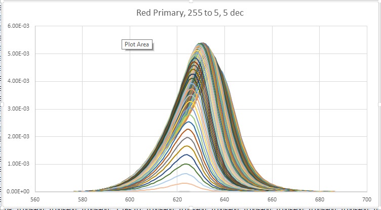
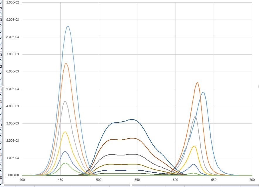
    Just FYI, I'm going to attach the light measurements I had taken from the Red primary between 5 and 255 inc 5, and from the R, G, and B primaries at a much courser resolution. The Blue and Green LEDs look like you might expect with small shifts in the peak wavelength as a function of current. However, the Red primary (this is obviously before we had all this trouble) looks very different and, in reality, the highest intensity red value was at 190, not 255. Plus there is a very strange shift. Might we have had a defective unit from the getgo (all measurements taken before it stopped working)?

    Best,

    Jim