This thread has been locked.

If you have a related question, please click the "Ask a related question" button in the top right corner. The newly created question will be automatically linked to this question.

EMI issues on DPP6401 solution

hi TI experts,

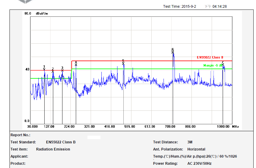
 I have a product which is used a DPP6401chipset , i am meeting a trouble on EMI test without an available solution to fix it for 720MHZ emission ,i found it was

radiated out between DPP6401 to DMD(0.45) ,i has tried to debug the parameters of the oscillator  R,C, add the bead cores or change the value  on VCC

cicuritry of DMD&DPP6401,but no obvious effects . i found  there was obvious effects when added bead cores on the trace between DPP6401 and DMD ,but the

720MHZ can't be under the spec yet . do you have any good ways to fix it well ? 

thanks a lot .

  • Hi Jack-sun,
    The 720MHz appears to be a multiple of the DMD Data Clock, 120MHz (6x 120MHz = 720MHz).
    Although I am a little surprised that the peak at 720MHz is higher than at 240 & 480MHz. So there may be some other effect or cause going on too.
    Have you tried changing the input pixel clock rate to see if that has any effect?
    The primary way to reduce the EMI from the electronics is to enclose it in a metal or metalized-plastic enclosure. This would give the biggest attenuation of any EMI for the whole product.
    There are other methods of reducing the EMI from the DMD clock:
    1) Route the DMD_DCLK and all of the date lines on internal layers of the board, between ground planes. Use as few vias as possible to avoid points at which the signal can radiate.
    2) Any connectors or flex cables can also allow significant signal radiation if not designed correctly.
    For any flex cables, use a ground plane. Also use a metalized overcoat (e.g. silver epoxy layer) or sheath to reduce EMI.
    3) You can also use a different DMD clock frequency (206MHz) which will shift the frequency peaks. NOTE: This would also require use of different sequences specifically designed for this clock frequency. It may just shift the peaks and not reduce them any.
    4) Any metal or metalized covers, coatings, sheaths, etc., should be well grounded to help reduce any signal radiation.
    Regards,Roger
  • hi Roger,

       thanks so much for your replys ,i will modify the Dclk route as you mentioned to check the result .

    Regards,Jack

  • would you please tell me how to change the clock frequency by command ?
  • Hello Jack,

    Do you use DLP Composer?

    What command interface are you using?

    Roger

  • hi Roger,
    I am using the composer of DPP6401 or I2C over a front chip comniucates with the DPP601 .
    B/R
    Jack
  • Hi Jack,

    The DMD clock setting is an internal operation, it's controlled by the ARM SW. We don't have I2C command to change the DMD clock. Sorry about that.

    Regards,

    Frank Xu

  • hi Frank,

     Anyway ,thanks to you .