This thread has been locked.

If you have a related question, please click the "Ask a related question" button in the top right corner. The newly created question will be automatically linked to this question.

I2C command ACK Delay

Other Parts Discussed in Thread: DLPC350

Hello ALC team,


I have a question about the I2C specification of DLPC350.


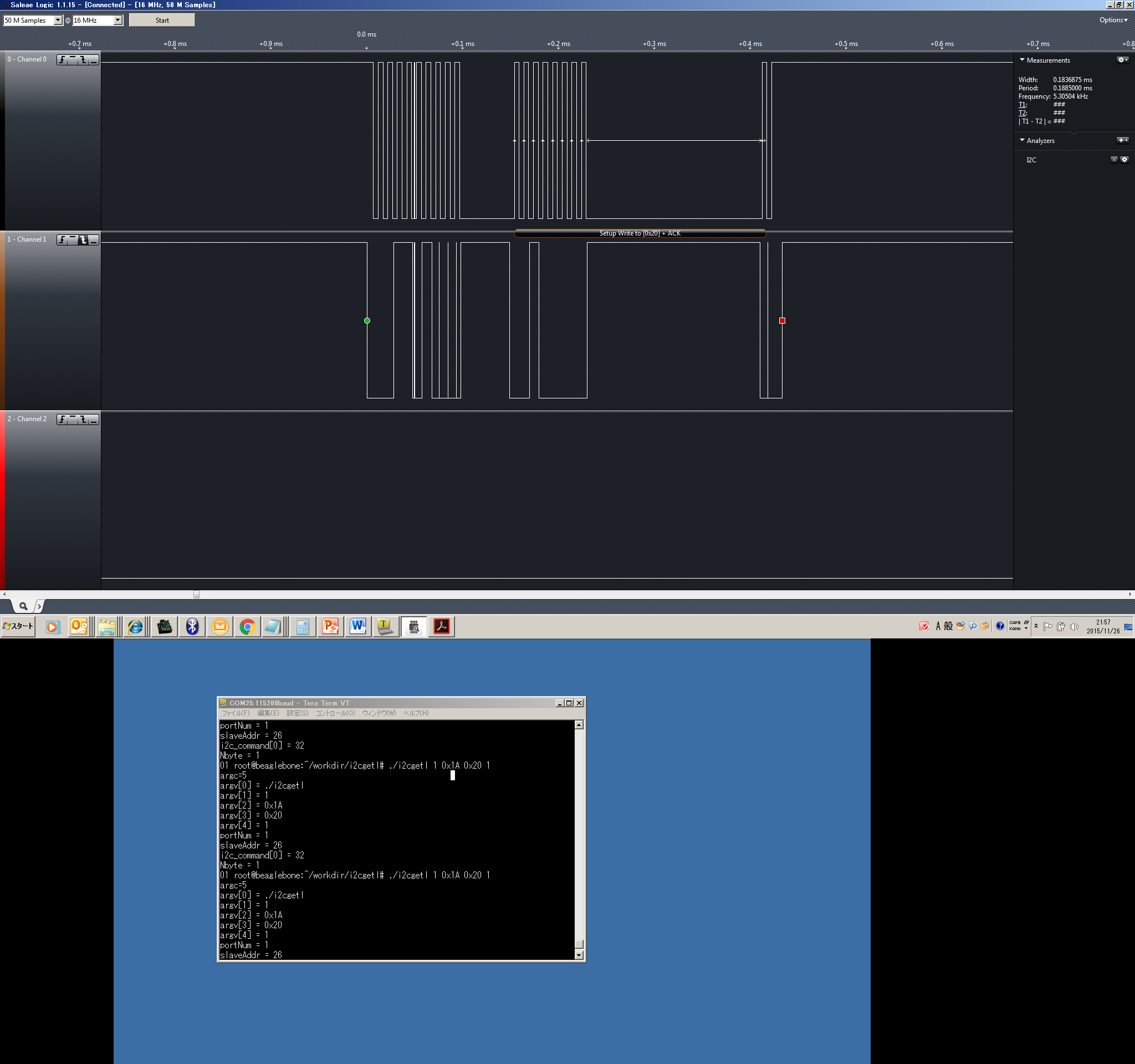
It looks ACK response from DLPC350 is delayed when I2C communication is done.

For example, to read the hardware status (0x20), the communication should be as follows;


Expected result : ST 0x3A A 0x20 A SP

Actual result   : ST 0x3A A 0x20 ------------A


It looks the ACK is delayed about 180 us after 0x20 is sent. Please see the figure below.


ST = Start Condition

A = ACK

SP = Stop Condition


Q1:

It looks SCL is fixed to Low and SDA is fixed to High until ACK is returned.

Does this mean I2C WAIT specification is used?

During this period, is it the status that DLPC350 side is driving SCL and SDA signal?


Q2:

If DLPC350 side is driving SCL and SDA, after the DLPC350 outputs ACK with delay, does DLPC350 release driving these signals soon?


Q3:

After ACK is output with delay, DLPC350 would wait for receiving the Stop Condition from the host MPU.

Does any timeout to wait for Stop Condition exist in DLPC350 side?

If a timeout exists and occurs, is there any possibility that the DLPC350 is continuously driving SCL and SDA?


It would be helpful if you have any comment on these questions.


Best Regards,

Nobu Arai

  • Hello ALC team,

    I have got additional questions about the I2C specification.
    Would you also please check the following questions?

    Q4:
    It looks the delay of getting ACK depending on the kind of commands or there is a variation of this delay time.
    For example, the delay time is 180us in the case of I2C command 0x20 but it is a little longer in the case of other commands.

    So, would you please tell us the maximum delay time?
    In order to avoid the dead lock, it would be helpful if you can provide the information of worst case of this delay time.

    Q5:
    We have a question about the stop condition in the case of reading the DLPC350 register by I2C command.
    After the first writing of the address, is the stop condition really needed?
    It looks reading the register is succeeded even if there is no stop condition between Write and Read.
    Would you please give any comment on this?


    Best Regards,
    Nobu Arai
  • Q1: Yes

    Q2: Yes

    Q3: NO; there is no timeout exist for receiving a STOP signal

    Q4: The I2C command handler performs the search for the valid command # ; you can expect the worst case delay when you issue an invalid command #.

    Q5: Once receiving the entire command message the controller goes ahead with processing the command without waiting for the stop condition; so it is optional.

    Regards,
    Sanjeev
  • Hello Sanjeev-san,

    Thank you for the answer.

    Please let me ask an additional question about Q4, worst case delay time and Q5, stop condition.

    Regarding Q4;
    I understood your answer that the worst case delay time is when the invalid command number is issued.
    However, I do not know what command number is really invalid command because it may be a hidden resistor that is not written in the programmers guide.

    So, is it possible to provide any actual number of worst case delay time?

    For a quick confirmation in my side, if I issue the I2C 0xFF command for example, it looks the delay is about 400 us.
    But I do not know whether this is the worst case. So, it would be helpful if you can provide the actual value of the delay time.

    Regarding Q5;
    Thus, do you mean they do not need the stop condition between Write and Read?
    Is it possible to explain the reason why this option is existing?

    Thank you very much for your help.

    Best Regards,
    Nobu Arai
  • Q4: 400us is worst case. 0x7F image load command is the last command list.

    Q5: This is the design decision.

    Regards,
    Sanjeev