This thread has been locked.

If you have a related question, please click the "Ask a related question" button in the top right corner. The newly created question will be automatically linked to this question.

3D Scan gives wrong point cloud

Other Parts Discussed in Thread: TIDA-00254

Hello,

I'm trying to create a point cloud using the software found here: http://www.ti.com/tool/tida-00254

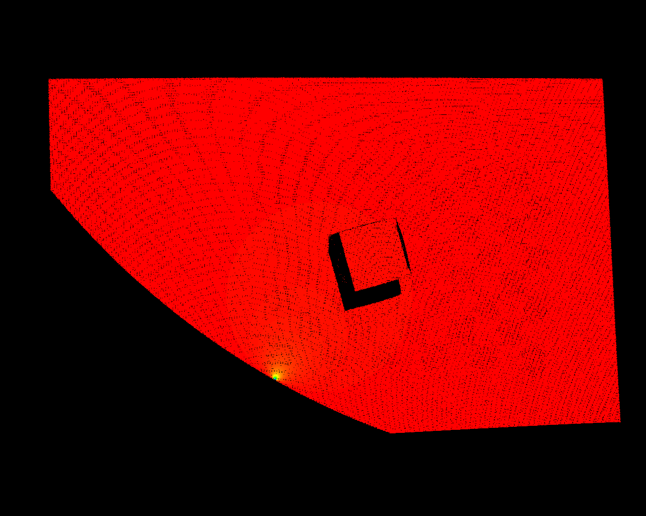
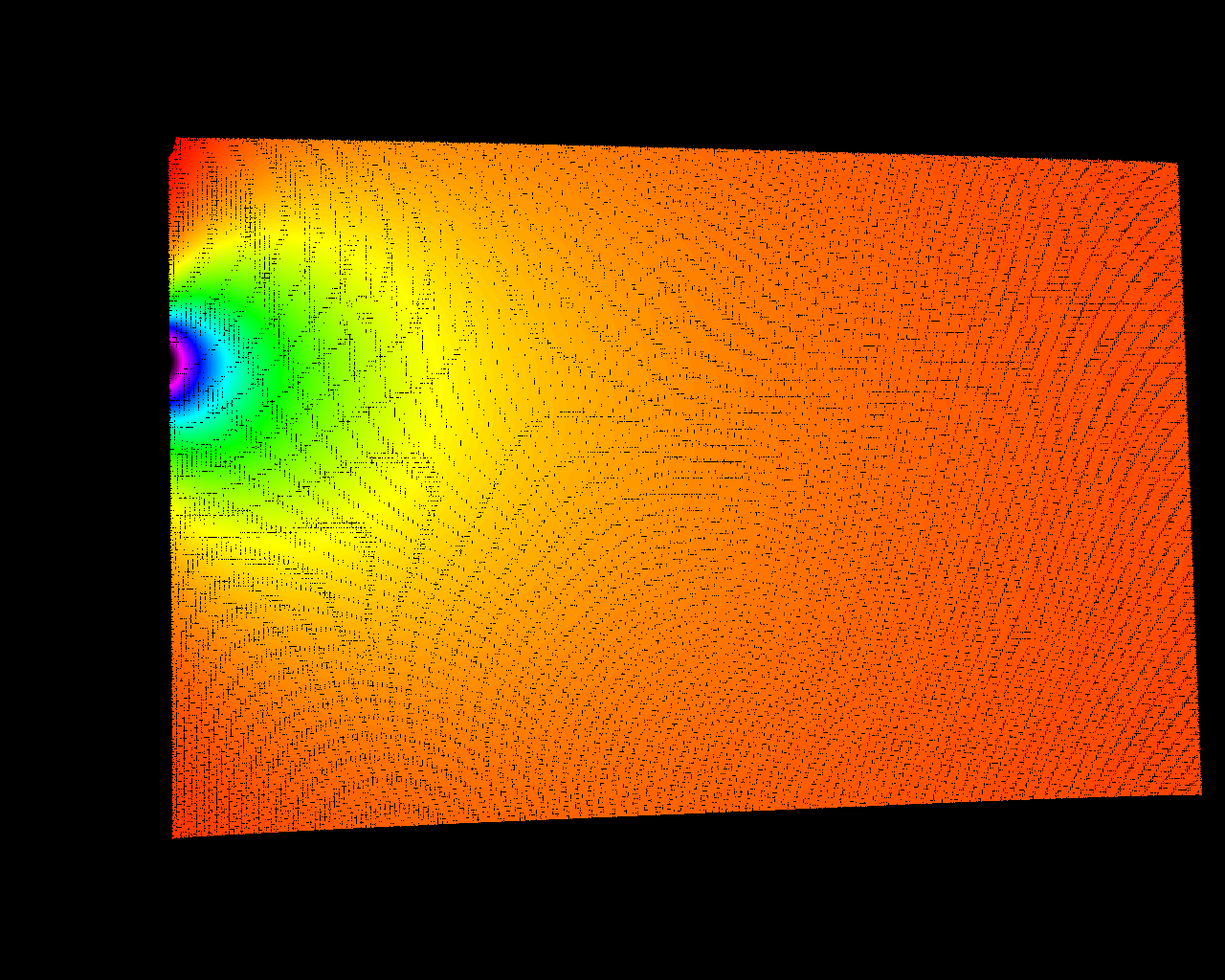
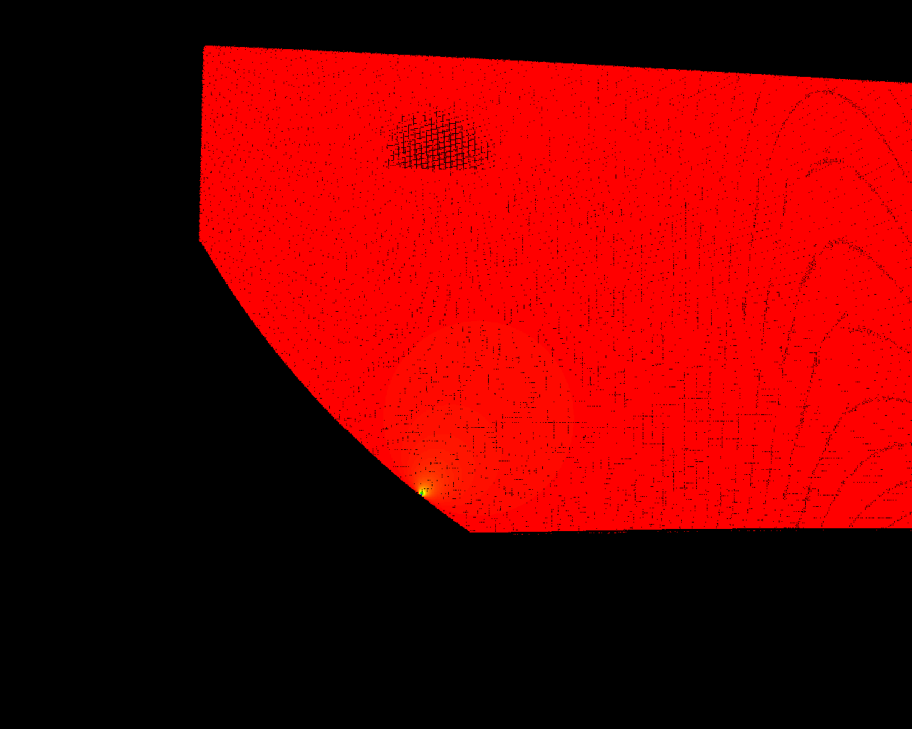
When I scan a flat surface, I get the following depth map:

For some reason, it isn't flat. When we view the point cloud in meshlab we get this result:

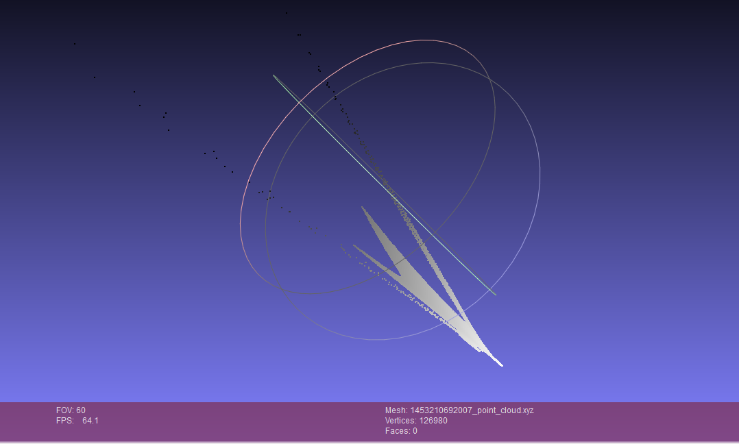
These are all wrong and I don't know why.

I've calibrated the camera with a reprojection error of 0.300224 and the projector with a repojection error of 1.10386852


Is there a solution to this problem?

<reprojection_error>3.0022461246092108e-001</reprojection_error>

  • Hi Sander,

    Based on your projector reprojection error, your system calibration could be the issue. Could you post a photo of your setup? I would like to get an idea of the camera to projector orientation as well as how you are keeping the system locked in place once you complete calibration.

    If you could zip and post your calibration folder, that would be useful as well.

    Thanks,
    Clinton
  • If you could include a zip of the output folder (images and point cloud), that would be helpful too.
  • Hello Clinton,

    Thanks for the fast response.


    Here are all the files you asked for:

  • I'm still struggling with this problem.

    I recalibrated the system so the camera has a reprojection error of 0.117302 and the projector reprojection error is 0.443832.

    This is the depth image I get when scanning a flat surface:

    Does anyone have a solution or an idea?

    Regards,

    Sander

  • Hi Sander,

    Thanks for posting your calibration and scan files. I have a few comments:

    1. It looks like you have a glare on your scan surface, which could cause the points to be incorrectly mapped in the point cloud. The original screen shot you posted would be indicative of this. You will want to remove this glare.
    2. Could you follow the calibration process as outlined in the user's guide for the design? It appears you are only moving around a printed calibration pattern around on flat surface, as apposed to:
      1. For camera calibration: moving the camera around
      2. For the projector calibration: moving the calibration board to different angles in the z-direction

    Please see the user's guide for additional details.

    Thanks,

    Clinton

  • Hi Clinton,

    I followed your advise and reduced the glare.
    I also made sure to move the calibration board this time. For the camera calibration I used the option to calibrate the camera alongside the projector (option 5, update camera intrinsic and distortion data).
    My camera reprojection error is 0.15 and my projector reprojection error is 0.44.

    I still get erroneous results, as you can see in the following depth map:

    Here are also all of my output files and my config files.

    www.dropbox.com/.../PC Sander Grielens.zip

    Hope to hear from you soon,

    Sander

  • Hi Sander,

    Thanks for posting your data. A few observations:

    1. It appears for the camera calibration images, you are moving the checker board around.
      1. Leave the checker board stationary at your desired scan distance and unmount the camera
      2. Then hold the camera at various angles to take captures like those found in the user's guide
    2. I cannot tell for sure, but it looks like maybe you are moving the projector around during the system calibration to get the angled shots
      1. It is important that before the system calibration the projector and camera are locked into position and do not move in relation to each other once you start the system calibration
      2. You should not be moving the checker board around the surface, rather you should be moving the surface at different angles, as is shown in the user's guide
    3. The BMP images of your point cloud look very different (have many more points) than your point cloud data (XYZ file).
      1. This seems odd to me

    Please try re-calibrating with the suggestions above. You may also want to ensure there are not any issues with your camera sensor and/or your camera lens.

    Thanks,

    Clinton

  • Dear Clinton,
    1 a/b. We are following dlpu019.pdf which is the user manual for TIDA-00254. The manual clearly states on page 28 point 9 to move the calibration BOARD to various positions and angles. This is what we have done. Are you suggesting this manuals instructions are incorrect?
    2. a. We kept the projector and camera locked into position during the calibration procedure
    2. b. Page 42 point 5 of the user guide clearly states that various angles AND POSITIONS of the calibration board should be captured. This is what we did. Are you suggesting the instructions are incorrect?
    3. The BMP and pointcloud indeed look different because of the outlier data caused by the error we are trying to fix. However, the BMP and pointcloud do contain the same data.

    Kind regards,
    Wim
  • Hi Clinton,

    1 a/b. We are following the user guide for TIDA-00254: dlpu019.pdf. The guide states on page 28 point 9 "position the calibration board at varying angles, and in different areas". This is exactly what we have done. Are you suggesting (are you sure?) these instructions are incorrect?
    2 a. We are not moving the projector and camera in relation to eachother.
    2 b. The guide states on page 42 point 5: "capturing various angles and positions of the calibration board by rotating and moving the calibration surface". This is exactly what we have done. Again, are you suggesting the instructions are incorrect?
    3. The BMP and pointcloud look different because of the large deformations caused by the issue we are trying to solve. The bmp and pointcloud contain the same data.
    4. We are sure there are no issues with camera sensor and/or lens.

    Wim Abbeloos
  • Any update? It has been over a month and there is still no solution. It seems like nobody can even answer us whether the provided software works at all. Can you please keep us informed and look into the issue urgently?

    Thank you,
    Wim
  • Hi Wim,

    In the camera calibration the default values
    CALIBRATION_SETTINGS_BOARD_FEATURE_ROWS_DISTANCE = 19.14285714285714
    CALIBRATION_SETTINGS_BOARD_FEATURE_COLUMNS_DISTANCE = 19.16666666666667
    changed to
    2375 and 2372.727272727273 respectively.
    How did you arrive at these numbers? Can you revert to the default values and try?

    Regards,
    Sanjeev
  • Hi Sanjeev,

    We tried a couple different measurement units. The first one is metres *10^-3 and the second is metres * 10^-5.
    We already tried reverting the units to milimetres, but to no avail.

    Regards,

    Sander

  • Hi Wim,

    We have been providing suggestions on the calibration and setup configuration as this seems to be the most likely source of your issues. We have many users successfully using the reference design SW. I would again suggest matching your camera and system calibration images as closely to those examples we provide in the user’s guide. Hopefully other users on the forum can provide some feedback if they have run into similar issues.

    Thanks,
    Clinton