This thread has been locked.

If you have a related question, please click the "Ask a related question" button in the top right corner. The newly created question will be automatically linked to this question.

VLED of DLPA3000 is not operate.

Other Parts Discussed in Thread: DLP3010, DLPC3438, DLPA3000

Hi

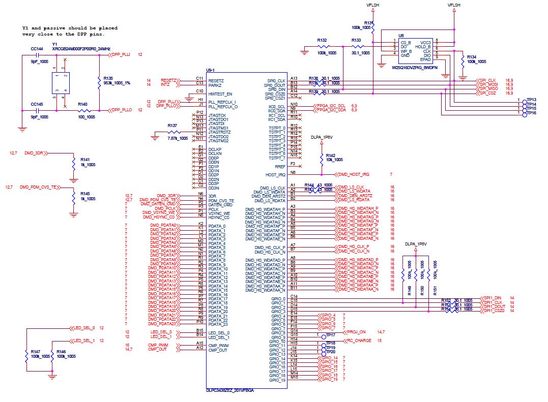
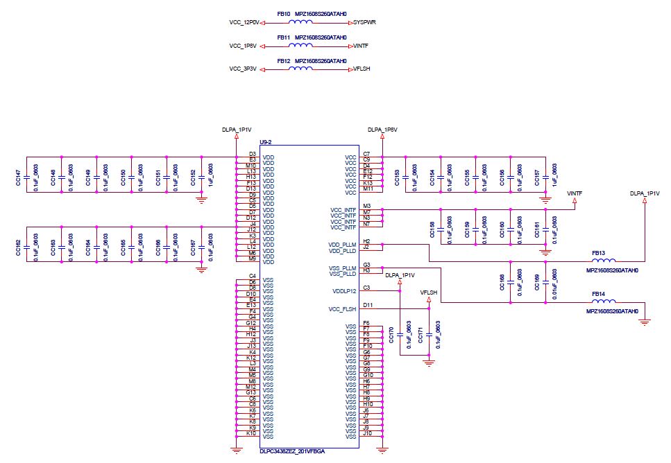
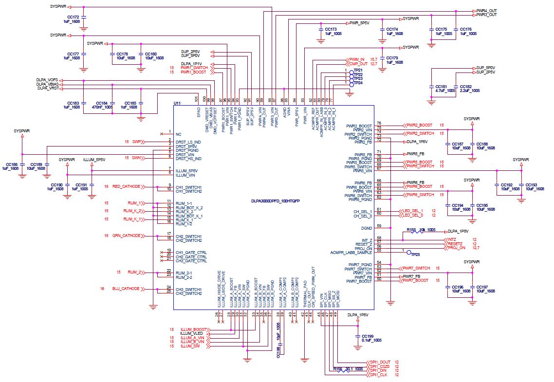
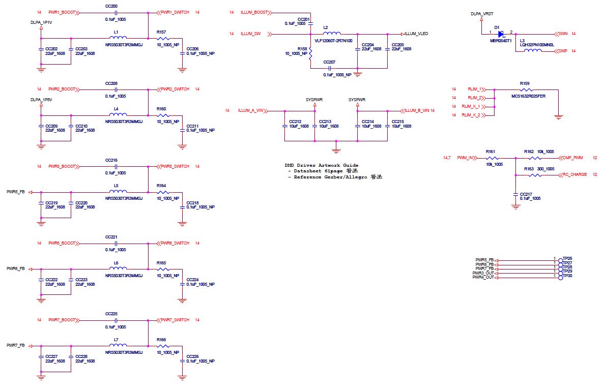
I use DLPC3438, DLPA3000, DLP3010.

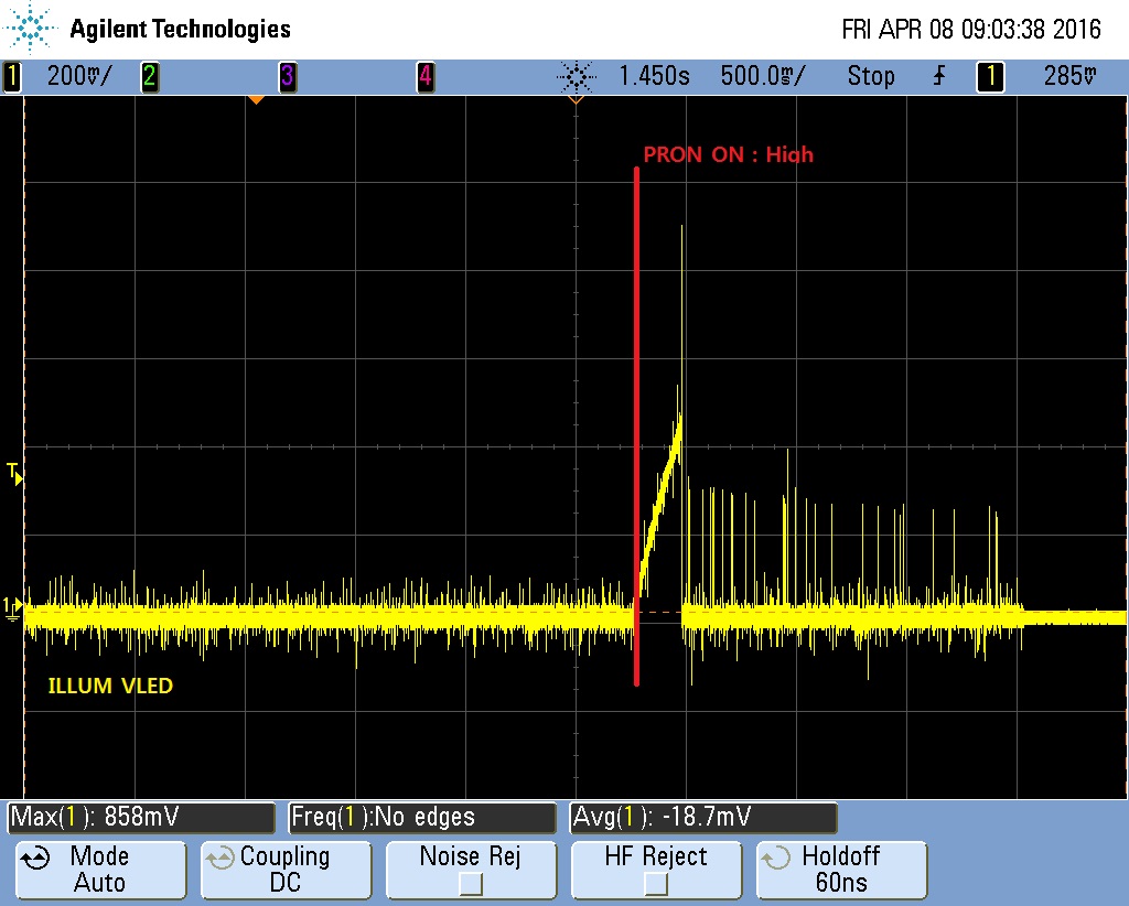
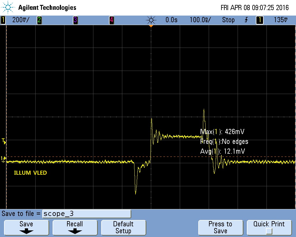
The problem is that VLED of DLPA3000 is not operate.

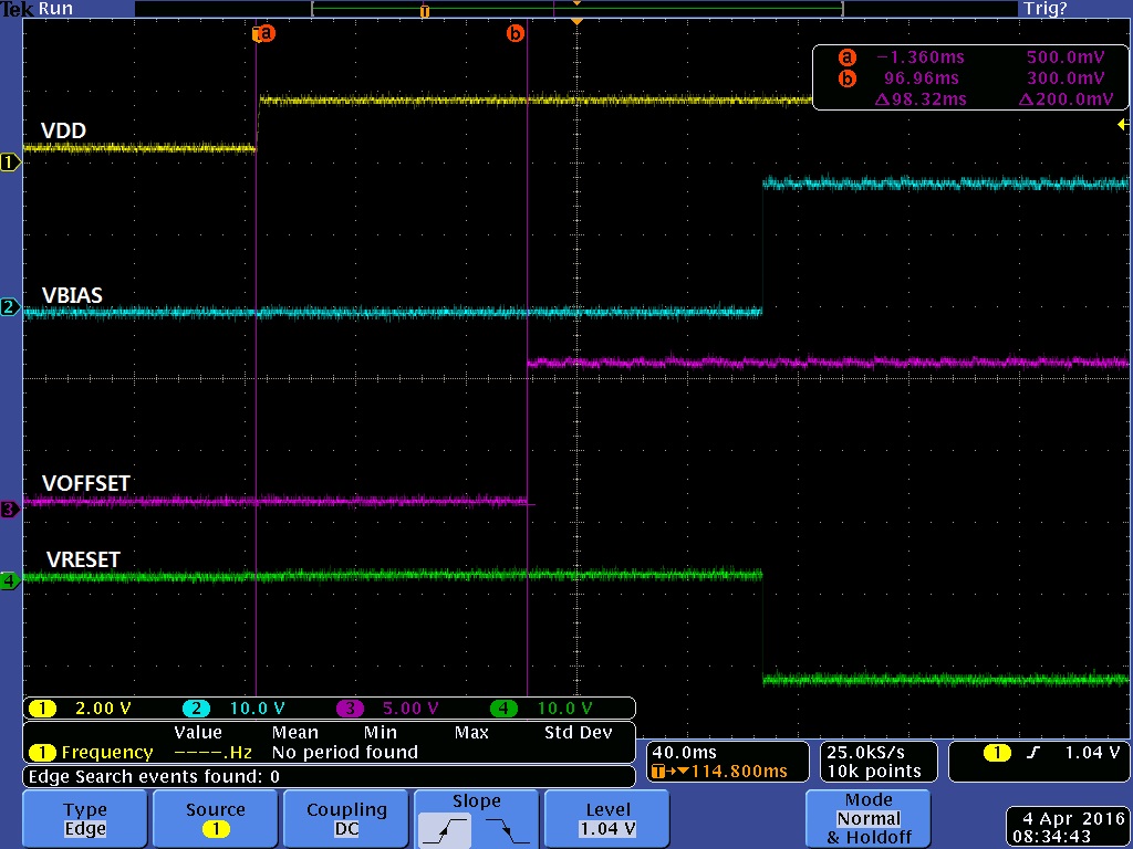
I expect that State of DLPA3000 is ACTIVE1. because voltage level and sequence of VRST,  VBIAS and VOFS is normally.

VRST = -14.25V

VBIAS = 17.58V

VOFS = 9.82V

[Sequence]

What should the state of DLPA3000 wonder whether the ACTIVE2.

SPI of DLPA3000 is connected SPI1 of DLPC3438. so I can't control ILLUM_EN (0x01 [1]).

  • Hello User,


    I am sorry to hear that you are having problems with the DLPA3000.

    I would like to take a look at your schematic to ensure that everything is correct on the hardware side.

    Can you please let me know what the desired LED current and the Input voltage of the DLPA3000 is ?
     

    Is VDD the input voltage to the DLPA3000 ?

    It would be helpful if you could provide the schematic of your board and the used software version.


    Best regards,


    Nadine

  • Thanks for your reply.

    Q1) Can you please let me know what the desired LED current and the Input voltage of the DLPA3000 is ?

    A1) Input voltage of the DLPA3000 is 12V [5A].

    Q2) Is VDD the input voltage to the DLPA3000?

    A2) No. VDD is DLPA_1P8V [PWR2]. Previous jped file is Input voltage of DLP3010.

    Below it is requested schematic file.

    The software version is expected that 00 00 0B 04. Because when the Read register [D2] of DLPC3438. 

    Flash version is 0A 00 0B 04 (Read Register : D9)

    Below is a review of information until now.

    In the 47page of the DLPA3000 datasheet seems to be the current state is ACTIVE1.

    The problem seems ILLUM_EN is not High.

    Our check was a 45page (table6) of the DLPA3000 datasheet, the result seems to be no longer, as in the previous inquiry.

    There are currently schematic ACMPR associated circuit remains a Test point. We are referring to a circuit TI LightCrafter Display 3010 separately but still VLED is not operated.

    Below is a waveform measured VLED.

    Q) When read DMD Device ID(D5h), we get data [60 0D 00 72]. below DMD Device ID is [60 0D 00 68].

      What do something wrong?

    Thanks

    Best regards,

    Kim ki-heon

  • Hello User,


    Thank you please allow me some time to review your schematic. In the meantime can you please send me scope plot which shows VLED and VIN ?


    Can you also please try to reduce the LED current during power up and let me know if the behavior is changing ?


    What value are you using for the RLIM resistor ?

    Also please note that currently PWR5 and PWR7 are not supported. Do you have anything connected to them ?


    We changed the DMD device ID to 72h. Your reading is correct.


    Best regards,


    Nadine

  • Hello User,

    I looked over you schematic and it looks good. Since I only see the schematic I want to point out that the RLIM_BOT_K should be connected to the bottom of the RLIM resistor.

    What firmware are you using on your system ?

    Best regards,

    Nadine
  • Thanks for your reply.

    I have solved this problem.

    Value of RLIM resistor is 25m[Ohms].

    Problem is warning of Schematic [ILLUM_A_VIN, ILLUM_B_IN].

    ILLUM_A_VIN and SYSPWR art not connected.

    Once again thanks for your reply.

    Best regards.

    Kim ki-heon


  • Hello Kim,

    Ok great. I am glad the problem could be solved.

    It looks connected in the screenshot you have send me.

    Best regards,

    Nadine