This thread has been locked.

If you have a related question, please click the "Ask a related question" button in the top right corner. The newly created question will be automatically linked to this question.

Error: DLPC900 Programming with UM232H

I got some issue in programming with JTAG, UM232H.

I wish to flash the memory of the EVM as it was interrupted once.

I connected the boards as the instruction in handbook Chapter 3.10 JTAG Flash Programming.

I have followed all the steps and it seems all good. When I clicked Flash Info button, it says:

Device parameters are not there (or correct) in the board file.

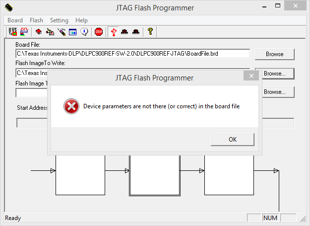
I just get stuck here and dd not know how to solve this problem.

Just wonder if anyone would have came across the same problem and solved it.

  • Hi Hanqing,

    Sorry for the delay. I have a couple of questions.

    1) Are you powering your board for this process?

    2) Does the Power Good LED come on when the board is plugged in?

    3) Do the red and green LEDs come on when the JTAG programmer UM232H is connected as documented in the instructions?

    Thanks,
    Trevor
  • Thanks Trevor! Here are the answers:
    1) Yes.
    2) No. Because a jumper has been installed on J9.
    3) Yes. Both LEDs are lighted.
    After I restart the computer, the problem above is solved. And I could see "connected" in system control panel in DLP LightCrafter GUI.

    But there are still some problems when I wish to follow the Chapter 2.2 in user's guide to create a simple pattern sequence.

    It says Unable to switch to pattern from Memory mode.
    I have upload a snapshot here:

    I have no idea why is that. Do you think it might have some problems in hardware?

  • Hi Hanqing,

    I'm glad your first issue was resolved!

    Now to talk about your current question, I see that in your screenshot, the firmware listed on the left side of the GUI does not contain a firmware version or tag. After you loaded the bootloader on your board through JTAG, did you then load the firmware on the board through the GUI?

    The bootloader build is just designed to bring up the board so that the firmware file can be loaded over the much faster USB interface. Firmware upload can be handled in the Firmware tab in the upper right of the GUI.

    Best regards,
    Trevor
  • Thanks! After the firmware is uploaded, I think it works normal now.