This thread has been locked.

If you have a related question, please click the "Ask a related question" button in the top right corner. The newly created question will be automatically linked to this question.

DLPC300 Internal Test Pattern (0x11)

Other Parts Discussed in Thread: DLPC300

We are developing a product using the DLPC300 controller. The video input is from a PAL to BT656 decoder and the I2C interface is managed by an AT32UC3B0256 microcontroller. The controller powers up and performs internal initialization. After releasing RESET and PARK, INIT_DONE goes high and after a while goes low again. When reading the DLPC status register, the device ID and initialization status are reported correctly. I can set registers and read back their values to confirm correct settings.

What are the minimum register settings required to display a checkerboard pattern (option 0 of Table 2-25 in dlpu004b.pdf)? Should I be able to see the test pattern without the video decoder decoding a valid signal? I also don't want the DLP controller to drive any of the LEDs. The idea is that the controller sends a signal to the mcu which then drives an LED through its PWM.

Any assistance would be much appreciated.

Johan

  • Hi Johan,

    Welcome to the DLP forums and thanks for your question! I don't think that I'm following what you're asking. Why do you want to display the internal checkerboard pattern AND use a video signal? The internal patterns don't require any input from video to be properly displayed, which I believe answers your question about the video decoder getting a valid signal.

    To disable the LED driver in the DLPC300, you'll have to use the RGB LED Enable Register (0x16, section 2.2.6.2).

    As for the minimum register settings, the following should work:
    0x0B //Input source and interface mode select
    0x0C //Input resolution select
    0x0D //Pixel format
    0x16 //RGB LED enable/disable
    0x11 //Select internal test pattern

    Give that a shot and if it doesn't work, let me know.

    Thanks,
    Paul
  • Hi Paul,

    Thanks for the prompt response.

    I wanted confirmation that the test pattern is independent from a video input which you did in your answer.

    I just tried the following register settings:
    0x0B = 1 // test pattern input source
    0x0C = 19 // 854 x 480 WVGA (Is there no way that this could work with 608 x 684?
    0x0D = 2 //Pixel format RGB888
    0x16 = 0 // LEDs disabled
    0x11 = 0 // checkerboard pattern

    Before setting any of the register, directly after INIT_DONE goes low, I read the status register and the device ID is 0x8A.

    After setting each register, the register is read back to confirm that the value is correct. After setting all the above registers, the MCU enters an infinite loop.

    Currently, I can see all the mirrors change state (or flip), but no pattern is observed.
  • I think that the following will work a little better:

    0x0B = 0x1 //test pattern input source
    0x0C = 0x13 //it does need to be in the proper resolution, only one resolution supports internal test patterns.
    0x0D = 0x2 //set correct pixel format
    0x4B = 0x00151624 //turn off the red LED enable signals.
    0x4C = 0x25110000 //turn off the green and blue LED enable signals.
    0x11 = 0x0 //checkerboard pattern.

    I tested this on my unit and it worked for me, I hope it works for you too.

    Paul
  • I tried these setting without any luck. If I look closely at the DMD I can see the mirrors moving randomly.

    I also tried doing 0x2D = 0x0 but it makes no difference.

    Could the flash config be wrong somehow causing this problem? The config binary supplied by TI is 2 MB but our board is fitted with only 1 MB. I uploaded the first 1 MB to flash (and verified) so I'm pretty sure it has the correct settings. Would I have gotten this far if it wasn't correct?

    Johan

  • Johan,

    Do you have a Lightcrafter EVM that you can test with? If your memory isn't large enough to support the fully binary config, that is likely going to cause a problem.

    Paul
  • Here's something else I would recommend you try. Go through the programmer's guide for the DLPC300 and test some of the register settings and see how many of them work. I know not all of them will apply, because you're not using the LED driver in the same way, but perhaps you'll be able to assess the functionality of the configuration binary that way.

    Paul
  • Unfortunately not. We had one but it got destroyed by overvoltage :(

  • I will try and get a large enough flash chip in order to rule out the possibility of that being an issue.

    Not sure what you mean about testing . How would I go about testing the registers? Do I need to just read their default values?
  • That would work - see how many default values you can read and see if you can write to any registers as well. This might give you a sense of how "complete" the FW is with only 1MB of the configuration binary.
  • Hi Paul,

    Thanks for your help so far. It is much appreciated.

    Below is a list of values read from all DLPC300 registers at startup. Some are correct but others not.

    I then proceeded to setting the correct values for the registers that weren't set to default before setting any other registers specific to obtaining a test pattern. No difference could be observed.
    How is the config file generated. Is there a possibility of TI providing a file with just the minimum settings needed?

    Note: Before writing config data to the flash chip, a complete chip erase is performed.

    R   Read       Expected (Table A-1 in dlpu004b)
    00: 0x00000000 n/a OK
    01: 0x00000000 n/a OK
    03: 0x00000A8A 0x8 OK
    0B: 0x00000002 0x2 OK
    0C: 0x00000003 0x1 !
    0D: 0x00000002 0x2 OK
    0E: 0x00000000 0x0 OK
    0F: 0x00000000 0x0 OK
    10: 0x00000001 0x0 !
    11: 0x0000000D 0xD OK
    12: 0x000002EE 0x03FF !
    13: 0x000002EE 0x03FF !
    14: 0x000002EE 0x03FF !
    16: 0x00000007 0x0 !
    19: 0x00000859 0x0859 OK
    1D: 0x00000000 0x0 OK
    1E: 0x00000000 0x0 OK
    1F: 0x00000000 0x0 OK
    23: 0x00000005 0x5 OK
    29: 0x00000000 0x0 OK
    2A: 0x00000000 0x0 OK
    2B: 0x00000000 0x0 OK
    2C: 0x00000000 0x0 OK
    2D: 0x00000000 0x0 OK
    30: 0x00000000 0x0 OK
    33: 0x00000000 0x0 OK
    38: 0x00000000 0x0 OK
    39: 0x00000000 0x0 OK
    3A: 0x00000000 0x0 OK
    4B: 0x1E1D1C1B 0x0 !
    4C: 0x0036001F 0x0 !
    50: 0x00000007 0x6 !
    52: 0x00000001 0x1 OK
    53: 0x00000001 0x1 OK
    54: 0x00000028 0x28 OK
    5E: 0x00000001 0x1 OK
    5F: 0x00000100 0x100 OK
    60: 0x00000011 0x0 !
    61: 0x00000029 0x0 !
    62: 0x00000000 0x0 OK
    63: 0x00000100 0x100 OK
    64: 0x00000000 0x0 OK
    65: 0x00000000 0x0 OK
    66: 0x00000000 0x0 OK
    67: 0x00000100 0x100 OK
    71: 0x00000100 0x100 OK
    72: 0x00000100 0x100 OK
    73: 0x00000100 0x100 OK
    7E: 0x00000000 0x2 !
    82: 0x00000001 0x0 !
    83: 0x00000200 0x0 !
    9B: 0x00000000 0x0 OK Note - How can I tell if BIST is enabled (see Table 2-4)
    A3: 0x00000000 0x0 OK
    A4: 0x0000000E 0xE OK
    A6: 0x00000000 0x0 OK
    A7: 0x00000000 0x0 OK
    AE: 0x00000000 0x0 OK
    AF: 0x00000010 0x10 OK Note - Table 2-14 does not correspond with this
    B0: 0x00000000 0x0 OK
    B1: 0x00000017 0x17 OK
    C3: 0x00000000 0x0 OK
    CF: 0x00000000 0x0 OK
    D0: 0x33221100 0x0 !
    D1: 0x77665544 0x0 !
    D2: 0xBBAA9999 0x0 !
    D3: 0x00EEDDCC 0x0 !
    D4: 0x000001E1 0x0 !

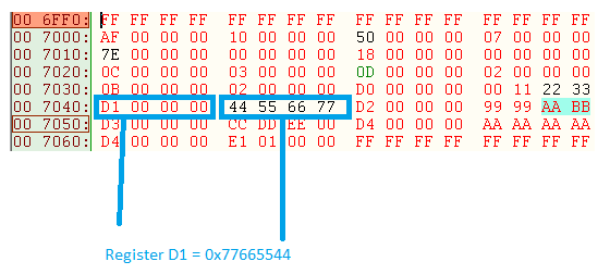
    I also searched for some of the byte patterns in the config file that I downloaded from the DLPC300 page (DLPR300PROM_v1.0.bin). The attached image shows what I believe is the default value for register D1. 

  • Johan,

    Unfortunately we're not able to provide an alternate version of the binary at this point. Ultimately I think the only solution in this case is going to be more memory so that you can load the entire config file to the DLPC300. I realize that's not an entirely satisfying answer, but I'm not sure what else I can recommend at this point.

    Paul
  • Thanks Paul,

    We are in the process of getting a larger flash chip. In the mean time I'm still confused by the fact that the register settings in the TI config file is different from what is specified in the programming manual.
  • Are you referring to 0xAF? My Lightcrafter unit also returns 0x10 as the default value, I'll make a note to add that to the programmer's guide documentation, thank you for pointing that out.

    Paul
  • Yes, but that's not the only one. 0xD1 also has a different value.

    I searched for the value and found the following sequence at address 0x007040: D1 00 00 00 44 55 66 77

    This confirms that the register value did indeed came from the config file.

    Another thing that confused me is Table 9 of the DLPC300 datasheet (doc nr DLPS023C). The table lists flash devices as low as 4 MB as compatible. Why are these devices listed when they clearly won't work?

  • Hi Paul,

    We tried a larger flash chip today (2 MB to hold the entire config file) but it made no difference :(

  • Hi Johan,

    I'm sorry to hear that the memory change didn't solve the problem. I'll send you a friend request on E2E. Can I review your schematics? Send me private message once you accept my friend request.

    Thanks!
    Paul
  • Responding to your previous question - "The table lists flash devices as low as 4 MB as compatible. Why are these devices listed when they clearly won't work?"

    Can you elaborate here? It seems that we've been discussing 1MB and 2MB memory chips, so I'm not quite following.

    Paul
  • My apologies. The table lists a 4 Mb device (not 4 MB) which is only 512 KB.
  • Good catch! I missed that :) You're absolutely right about the inconsistency, I'll take a look at why that might be and ask the systems engineer for this project if he can help clarify.

    Paul
  • Hi Johan,

    I have a little more information to share with you.

    The reason why the DLPC300 datasheet recommends devices less than 16Mb is because it is possible to have a smaller configuration file under some circumstances. Those recommendations were made before the Lightcrafter was released.

    0xD1 has a different value because the DM365 writes to that register on startup.

    Typically, when we see issues with I2C commands, we suspect the I2C communication itself. Are you able to probe the I2C lines on your board and take some scope shots? if your pull ups are too weak for instance or if there is a noise source on the board, these things might cause problems. I would take a look at the I2C communication and see if you can glean anything.

    I'll review your schematic soon and get back to you.

    Thanks,
    Paul
  • Hi Paul,

    Thanks for clarifying the issue around 0xD1. Are there perhaps any other actions that the DM365 performs that I might be missing?

    I'll send traces of I2C register read and writes over PM.

    Thanks

    Johan