This thread has been locked.

If you have a related question, please click the "Ask a related question" button in the top right corner. The newly created question will be automatically linked to this question.

Controlling the DMD Flickering

Other Parts Discussed in Thread: DLPC900, DLPC300

Hello, TI E2E Community

We are using the DLP Lightcrafter 3000 for experimental purposes, and we are interested in controlling the flickering of the mirrors.

We know that in the DLP Lightcrafter 6500, we can stop the DLPC900 clock in a controlled manner by using pin TP14. The latter pin gives access to the clock signal (colleagues of ours have found a way of stopping the clock for a short time, releasing it every once in a while to avoid damage on the DMD, allowing a controlled flickering).

We were wondering if there is an equivalent pin on the DLP Lightcrafter 3000 board to do the same. That is, of having access to the clock signal.

If there is no such pin, do you know any way of stopping the clock in the DLPC300?

Regards,

Inigo

  • Hi Inigo,

    Welcome to the DLP forums and thanks for your question. Can you clarify for me what you mean by "stopping the clock"? You're interested in preventing the mirrors from switching between the ON and OFF positions? Are you able to elaborate on what type of experiment you're running?

    If you're using the Lightcrafter EVM, can you define a pattern sequence with 1 bit patterns that does what you are looking for? In this case, the GUI will hold the exposure for as long as you'd like with the mirrors in one position.

    Your description of the procedure you use for the Lightcrafter 6500 seems risky from a DMD lifetime and damage perspective, which is why I would not advise it for either EVM. However, there may be a way to accomplish what you're looking for via software.

    Thanks,
    Paul
  • Hi Paul, and thank you very much for your rapid response

    When I say "stopping the clock" I mean preventing the mirrors from switching between the position I told them to be at (either ON or Off, depending on the bit) and the flat/rest position. From what I understood from the discussions in this forum, the mirrors on the DMD must come to a rest position after some time (refreshing time).

    In our experiment, we have a laser and we use the DMD as a spatial light modulator to change the intensity profile of the former. We are interested in having completely static images for a specific time (between 200 and 500 ms). We have been using the "Stored Pattern Sequence" mode to set the desired exposure time for our images. The images we have been loading are 1 bit-depth bitmaps (so black and white). Unfortunately, we have been observing fluctuations on the intensity of the light reflected by the DMD that do not come from our laser and do not seem to respect the exposure time (we see the flickering at random times, not equally spaced).

    Our colleagues had the same problem, and they solved it with the idea I told you about. This software solution you talk about sounds really interesting, and it might be more suitable for our purpose. Could you tell me more about it?

    Regards,
    Inigo
  • Inigo,

    The software solution I was thinking of is what I described above - simply creating a 1bit pattern sequence in the GUI and setting the exposure to the desired amount of time.

    To clarify, you see the fluctuations of intensity while using the Lightcrafter 3000, not the 6500, correct? What is the variation in intensity? A few percent? More?

    I'm going to do some looking around on our side to see if I can get you a clear picture of what's going on.

    Thanks,
    Paul
  • Yes, I am using Lightcrafter 3000. The variation in the intensity is between 5 and 10 percent...

    Thank you,
    Inigo
  • Inigo,

    How many 1bit patterns are you using in your sequence? If you're using less than 96 images, you'll have one transition to switch between patterns and no mirror movement during the pattern exposure.

    Paul

  • Paul,

    I am only using one pattern. I also tried setting two patterns with the same image to see if this was a problem, but I saw the same fluctuations at unwanted times.

    So you are saying that, according to the configuration of the display I am using, no mirror movement should be seen between transitions. Is that correct? If that is so, I cannot think of any other explanation to the fluctuations I am observing...

    Inigo
  • Inigo,

    How are you measuring the fluctuation? Are you able to determine how often the fluctuation is occurring? Can you provide scope shots or data?

    Paul
  • Paul,

    To measure the fluctuation, I have placed a photodiode in front of the DMD, in the direction of the reflected beam (the one reflected by the on-state mirrors, in our case, black pixels). I see the photodiode's readings in an oscilloscope.

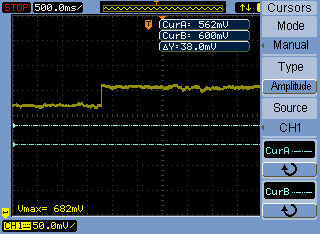
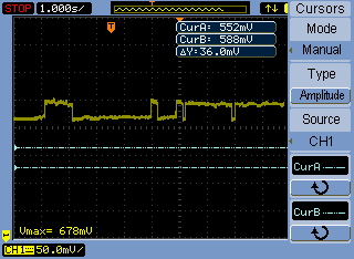
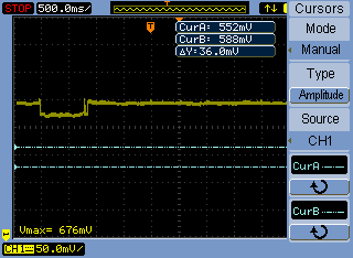
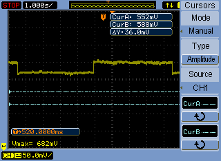
    I have set 10 images with the same pattern: every mirror is in the same on-state (the equivalent to 'Solid Black' in 'test pattern' mode) in "Stored Pattern Sequence", with an exposure time of 1s and a trigger period of 1001000 us.

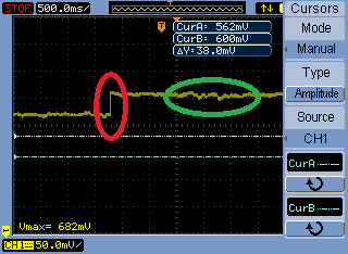
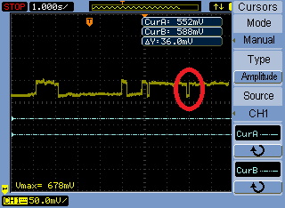
    I have attached four images taken with the oscilloscope. In each of them, the variation in the signal is a bit more of a 5 percent of the original amplitude. I have not been able to determine how often this fluctuation occurs: sometimes we have a stable signal for a long time (of the order of 10s) but still this time is never constant.

    Inigo

  • Inigo,

    Thanks for the scope shots. Just to make sure I'm understanding correctly, are you concerned about the fluctuations in the red circle (big steps) or the small fluctuations in the green circle?

    Or, if it's neither of those because the red circle (big step) is simply a state transition of the mirrors and the green circle (small fluctuations) are noise in the photodiode, then is it the behavior shown circled in the next image that is the concern?

    Thanks for the clarification,

    Paul

  • Paul,

    We are worried about the big steps.

    We expected the intensity to be constant during the exposure time, but in the shots you can see that these transitions change the intensity to a new constant value that extends for too long (recall that our exposure time is of 1s, while the time extension of this states is of 2-3 s).

    The red circle in the bottom image is also a problem, in the sense that we would like to know the times at which these transitions appear.

    Also, do you know what these state transitions are? Because we are loading the same images, I would expect the intensity not to change or only change during a short time between each picture (that is: after the exposure time, I would see a variation in the intensity for a short time).

    Inigo

  • Inigo,

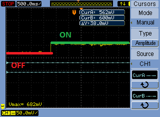
    I'm sorry, but I guess I'm still not quite following. In the picture below I've labeled OFF and ON states, but I think I'm actually incorrect. The OFF state should much further down the screen in your shot if I'm reading your scope screen correctly. You have a max value of 682mV and 50mV per division.

    The part is confusing me is the time scale - it's set to 500ms per division. If your exposure is set to 1s, then why don't we see a large transition between 0mV and 682mV for a mirror state change?

    Inigo Urtiaga said:
    but in the shots you can see that these transitions change the intensity to a new constant value that extends for too long (recall that our exposure time is of 1s, while the time extension of this states is of 2-3 s)

    Can you clarify what you mean by the above? You're not seeing behavior that reflects the desired exposure settings? This to me makes me wonder about your experimental setup. Are you capturing on your photodiode a large enough block of pixels that changes from ON to OFF such that the whole diode is covered? Your pattern could be turning only a portion of the pixels that the photodiode is measuring, causing your intensity to bump up.

    Setting the patterns to an exposure of 1 second is long enough the eye can differentiate between the patterns. As you watch the patterns change does it seem like they are switching correctly and with the right exposure? If it looks like they are, I would again suggest that perhaps there is something going on with the measurement setup.

    Some general information that might apply here: The pixels need a few 10s of microseconds to settle out between the transition of ON to OFF. In that time, you might see some slight variation in intensity between the patterns as the mirror bounces a little. However, on your timescale, it is unlikely that you'd see that behavior. Even in the case where the pixel doesn't change state between patterns there will be slight movement of the mirror, but it's typically only a few degrees.

    The Lightcrafter has been released in the field for about 4 years, we haven't seen any issues like this arise with the EVM itself. Can you confirm that you're using the latest version of the software and the firmware on your device?

    Thanks,

    Paul

  • Hi Paul,

    I think I did not make myself clear:

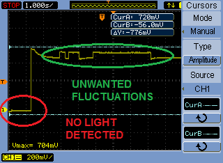
    Those states are not ON/OFF states. The only pattern I am loading into the DMD is a completely black image. Since, in our setup, black pixels correspond to reflected light, during the exposure time (1s) the DMD should be reflecting all the incident light into the photodiode (thus recording a high intensity).

    The low intensity level that you see in the shots does not correspond to zero detected light: It is precisely what we don't understand.

    I am attaching a scope shot I just took: I blocked the laser beam so that no light would reach the photodiode, and then I let the light arrive again. In the shot, you can see the time at which all the light is blocked (red) and the time at which it is detected again (green). As  you can observe, the fluctuations are there (5% in amplitude).

    (I chose the time scale to 1s because it was of the order of the exposure time and because we could see this weird state... Also, the voltage scale and the offset were completely arbitrary.)

    The reflected light is such that the whole photodiode is covered, so that should not be a problem.

    When I load different images (say, one completely black followed by a completely white picture), I can see by eye that the device is changing them in the correct time.

    When we bought the DLP Lightcrafter I downloaded the "DLP LightCrafter Firmware and Software Bundle" Version 3.0 (dated 12/5/2013), which I thought was the latest. Could you tell me if there is some update available?

    Thank you,

    Inigo

  • Inigo,

    I completely understand now, thank you very much for working through this with me. This problem is quite perplexing. Let me see if I can replicate this issue here on my Lightcrafter and I'll get back to you next week sometime.

    You have the most recent version of the SW/FW so that's great. If you have another Lightcrafter you could test with, give that one a shot and see if the results are the same on your setup.

    Thank you,
    Paul
  • Inigo,

    I cannot replicate this behavior on my Lightcrafter.

    You mentioned a laser - have you modified the Lightcrafter at all?

    Paul
  • Paul,

    We have removed the projector from the EVM, leaving the DMD (we did this following the instructions here: www.youtube.com/watch
    We send a laser beam to the DMD screen directly, and use the light that gets reflected.

    Inigo
  • Inigo,

    I'm completely at a loss for what might be causing this....perhaps if you sent us a picture of your setup?

    It is possible that these issues are caused by unwanted fluctuations on the V_BIAS line for the DMD. If you look at the schematics for the Lightcrafter (www.ti.com/.../dlp3000-c300ref), you can find TP35 and probe that point to see. Consult the Driver Board schematic for DMD_VBIAS.

    Thanks,
    Paul
  • Hi Paul,

    I found TP35 in the Driver Board schematics, but it seems that it is not labeled in our physical board. Because of this, I cannot find TP35 in our driver board (I found boxes U13 and U14, and even capacitors C57, C62, ... but TP35 is nowhere to be found). Is there any document with the names and locations of the pins on the boards? If we could have access to such a document, it would be extremely useful for future electronic problems. If not, could you indicate me where to find TP35?

    I send you a picture of our optical setup with a brief explanation that might help understand it better:

    I have a 5mW laser (780nm wavelenght) that is first coupled into a fiber (this is not in the picture). In the picture, in RED I show the path of the laser beam after it comes out of the fiber.

    I use a half-wave plate to change the polarization of the beam, and a polarizing beamsplitter that makes sure that only linearly polarized light passes through. This way, all the light that comes out of the beamsplitter is now linearly polarized.

    For our experiment, we want the light reflected by the DMD to be linear. Placing a quarter-wave plate and a half-wave plate before the DMD allows us to change the polarization of the linear light to any other polarization. We tune the plates in a way such that the beam coming out of the DMD is linearly polarized.

    The reflected light goes into a photodiode, which I have painted in blue.

    As you can see, the LightCrafter is mounted on a homemade box, to which the board is screwed. I have noticed that the connection of the DMD to the board is not very static in the mechanical sense (with this I mean that the DMD can move by simply touching its sides, as you can verify in your own LightCrafter). Maybe the fact that the DMD is not very static causes the beam to 'move' (i.e. to be reflected in a different direction) at certain times, and the photodiode does not catch as much light as before, causing a fluctuation. In fact, placing a CCD camera in front of the DMD, it looks as if the position of the beam moved at random times...

    Inigo

  • Paul,

    I just noticed I did not mention the beam damper in the explanation above: The light reflected by the 'OFF-state' and 'flat-state' mirrors goes to the beam damper, which simply blocks it.

    Inigo
  • Hi Inigo,

    Thanks for clarifying your setup. Let me look into how to access/open the layout files. They are included in the link I gave above, but I'm having trouble getting them open myself.

    The only thought I have on why those fluctuations might be occurring after seeing your setup is related to your comment about the DMD not being very static. Could vibrations in the lab be causing the photodiode to pick up some light that was intended for the damper?

    Thanks,
    Paul
  • Inigo,

    In the link above, there are .RAR files which contain the .PCB files that show the layout of the board. Use 7-ZIP or a similar tool to extract the .RAR files. To view the .PCB files, download PADS from Mentor Graphics. That program will allow you to find any feature on the board the corrospond it to the schematic and the physical EVM.

    Paul
  • Paul,

    I am sure there are no such vibrations in the lab where we keep the setup. Nevertheless, I am currently preparing a new mount for the LightCrafter which ought to eliminate unwanted vibrations. When the new mount is complete, I will be able to perform the same tests again.

    I am afraid that, from the experience of other colleagues, it is highly probable that we will keep having the same problem after reducing vibrations. When you give me access to the layout files, I will see if there is any fluctuation in the pin you mentioned. If we keep having the same problem we would like to explore the idea about stopping the clock, which we know has given results despite being harmful for the DMD.

    Inigo

  • Here is the link for PADS: www.pads.com/.../

    Thanks,
    Paul
  • Thanks a lot!

    Inigo
  • Hello again, Paul

    We built a new mount for the LightCrafter, which ensures that the DMD does not vibrate in unwanted ways. Unfortunately, we can still see the spatial movement of the beam. 

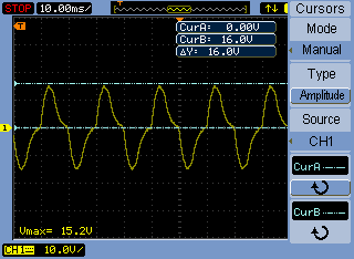
    I checked pin T35 and found the following voltage:

    It is an AC signal, and each peak has a 16V amplitude. The frequency is of 1/20ms  = 50Hz .

    Is this the expected behaviour on the device?

    Thanks,

    Inigo

  • I have attached a video of what we see with our CCD camera.

    As you can see, the beam keeps moving to the same spot, at unpredictable times.

    Inigo

  • Hi Inigo,

    Can you reattach the image of the voltage from TP35? It looks like it didn't embed properly.

    The behavior your video shows is certainly perplexing. These deviations you're showing wouldn't be the result of mirror resets and in order for the DMD to be causing these changes, the pattern would have to change.

    Are you seeing a corresponding mirror flips on the DMD? Can you send me a video of the DMD with the patterns sequence you've loaded running?

    Thanks,
    Paul
  • Actually, now that you mention it, I haven't been able to see if the mirrors are flipping or not. I will take a video and send it to you as soon as I can.

    Here is the voltage at TP35 again:

    Thank you,

    Inigo

  • Hi Paul,

    I am attaching 4 videos where the flipping of the mirrors can be seen.

    In the first two, I have loaded two patterns which consist of two circles of different radius, and I have set the trigger period to 1s. The time is  correct and the mirrors only flip when they are supposed to.

    In the last two, I have loaded the sequence I am using: two 'solid black' images with a 1s trigger period. The image looks static because it is the same pattern loaded twice, although there must be some refreshing at the end of the period. Once again, the mirrors appear to work fine.

    It has become clear to us that the flipping of the mirrors is not the cause of our movement, as you already pointed out.

    I have also noticed that small vibrations near the DMD result in big movements in the light beam, which are of the same order than the ones we are seeing. It appears that our problem might be of a mechanical nature, but we have not discovered the origin of the vibrations that could cause the movement...

    I was wondering if you have been able to reproduce this behavior in your LightCrafter. Also, is the signal at TP35 right?

    Thank you,

    Inigo

  • Inigo,

    I have not been able to reproduce this behavior in my unit and the signal at TP35 does look look correct. One thing with regard to TP35 would be to probe it during the flickering event and see if there is any change in the waveform at TP35. I don't think you'll see anything, because the mirrors clearly aren't moving, but that test would fairly conclusively eliminate any electrical cause of this issue.

    Paul
  • Hi Inigo
    Do you slove the mirror flickering problem on the dl3000?

    With kind regards
    Peter