This thread has been locked.

If you have a related question, please click the "Ask a related question" button in the top right corner. The newly created question will be automatically linked to this question.

LED becoes dark in the case of external trigger mode

Other Parts Discussed in Thread: DLPC350

Hello DLP ALC team,


I have got a question from our customer. It seems they are seeing the problem in LightCrafter4500.

Please see below and would you please give any advices to solve the problem?

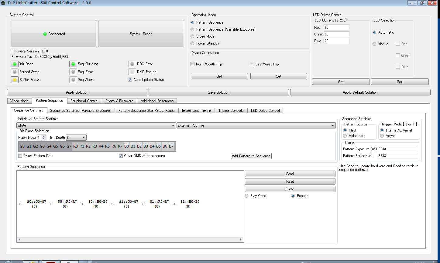
[LightCrafter4500 Configuration]

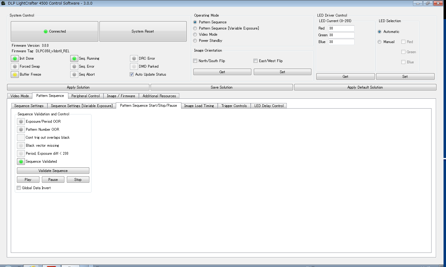
- Pattern Sequence Mode

- Color : White

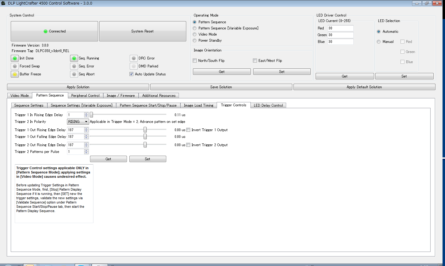
- Trig : External Positive

- Flash : index0, 1  8bit

- Pattern 8bit × 6

- Pattern Exposure: 8333us

- Pattern period : 8333us

- Trigger Frequency : 14Hz ~


[Problem]

Phenomenon 1

If they turn on and off the external trigger signal repeatedly, the brightness of the image becomes sometimes normal and sometimes dark.

A reproducibility is higher.

When the image is darker, it looks the waveform of LED current is inverted as compared to the normal working.


Phenomenon 2

Despite they set the external trigger mode, the internal trigger works and LED turns on (the image is displayed).

In that case, if they try to turn on and off the external trigger, the brightness of the image becomes sometimes normal and sometimes dark


[Question]

They are thinking that this may be the problem of the DLPC350 firmware.

Would you please give any advice to solve this issue or provide any workaround to avoid this problem?


Best Regards,

Nobu Arai

  • I am sorry for mistaking the place to ask. Would you please move it to the Lightcrafter4500 forum?

    Best Regards,
    Nobu Arai
  • Hi Nobu-san,

    We ran some tests here with the conditions that you described and did not see what you are describing. Would it be possible to attach a video of the phenomena you are seeing?

    "Despite they set the external trigger mode, the internal trigger works and LED turns on (the image is displayed)."
    Would you be able to elaborate on this? I don't understand what they are seeing. What does "the internal trigger works" mean?

    Thank you!
    Paul
  • I would like to add that if you are switching from external to internal trigger, you need to clear all the patterns in the sequence for the settings to take effect. This should solve phenomena #2.

    Paul
  • Paul-san,


    Thank you for the comment. I will try to get the video image from the customer.


    >> "Despite they set the external trigger mode, the internal trigger works and LED turns on (the image is displayed)."

    >> Would you be able to elaborate on this? I don't understand what they are seeing. What does "the internal trigger works" mean?


    Regarding the phenomenon #2, please let me explain again.


    They configure DLPC350 to external trigger mode and play the sequence.

    Then, they try to input the trigger from the external device and turn on and off the trigger repeatedly.

    After that, even if they stop the trigger signal (and they do not change any setting), the LED sometimes

    turns on and the image is displayed. They do not know whether the internal trigger works but the image is output without any external trigger signal.


    Anyway, I will try to get the video to see what the phenomenon is.


    Best Regards,

    Nobu Arai

  • Paul-san,

    I asked them to send the movie file of the phenomenon but they cannot send it yet and they will send it to us a couple of days later.

    By the way, they captured the waveform of the trigger signal and LED signals in both normal and bad cases.

    So, would you please check the attached waveforms and give any comment?

    We also got the capture image of GUI tool. Please also check whether there is any problem or not.

    It would be helpful if you can give us any comment.

    Best Regards,

    Nobu Arai

    LCr4500_LED_Waveform.xlsx

  • Nobu-san,

    The GUI configuration looks correct. I appreciate the oscilloscope screen-shots, they are very helpful. I think I understand better what the problem is and I will try my tests again to see if I can replicate. Please give me some time and I will reply back here on my results.

    Thank you,
    Paul
  • Hi Nobu-san,

    We exactly replicated their set-up and we are unable to replicate the issue - we would like to wait for the video.

    A few additional questions:
    1. The problem waveform doesn't make sense. The LED current is ON for much longer, which would give a very bright image, not a dark one.
    2. Why does the customer want to repeatedly turn on and off the external trigger?

    Could the customer please attach a screenshot of the "Trigger Controls" tab on the GUI? We would like to verify that everything is set as we expect it.

    Thank you,
    Paul
  • Paul-san,


    Thank you for the comment and testing to reproduce the problem.


    I will ask them to answer your questions and provide a video.

    But it is national holiday in Japan today. So, I will get back to you tomorrow.


    Thank you very much for your supporting.


    Best Regards,

    Nobu Arai

  • Paul-san,

    I got the movie files about these phenomena. But the size is too large to send. So, I upload a zip file to our ftp server.

    I will send you a friend request separately and send an information of the link. Would you please download this file and check the movies?

    There are two files in a zip file.

    1. Phenomenon_1.avi :  If they turn on / off the external trigger repeatedly, LED becomes sometimes dark and sometimes bright depending on the timing.

    2. Phenomenon_2.avi :  If they turn on / off the external trigger repeatedly, LED sometimes turns on even there is no external trigger signal.

    Please check these files and it would be helpful if you can give us any comment.

    Please also see the answer to your questions and request below.

    >>1. The problem waveform doesn't make sense. The LED current is ON for much longer, which would give a very bright image, not a dark one.

    In the problem case, the polarity of the waveform between normal and problem is opposite (reversal).

    It means that the LED becomes OFF during period of 8333us that LED should be ON and vice versa. That is why the image looks dark.

    >>2. Why does the customer want to repeatedly turn on and off the external trigger?

    It seems an end user is existing to our customer. Our customer received a report of this problem from their end user.

    Our customer does not know the details but their end user is using the Light Crafter 4500 with this type of usage (On/Off the external trigger repeatedly).

    >>Could the customer please attach a screenshot of the "Trigger Controls" tab on the GUI? We would like to verify that everything is set as we expect it.

    Please see the following capture of trigger control tab.

    We have got some additional information below.

    I asked the customer how they are switching the external trigger. As a result, we got the following information.

    - In the case of their end user

    The end user is using the USB type of parallel I/O interface unit. It seems the pulse is generated by pushing the PC keyboard continuously.

    - In the case of our customer

    Our customer is using the pulse generator and pushing OUT button to turn on/off the pulse output.

    The name of pulse generator is SG4322, made in IWATSU.

    In both cases, a relay switch may be used to turn on / off the pulse. It looks some chattering noise occurs when the pulse is generated.

    Please see the waveform of chattering below. I am wondering this may be related with the problem. So, would you please try to reproduce the problem by using some mechanical (hardware) switch to turn on /off the external trigger signal repetedly?

    I am also asking them to reject the chattering noise and check the phenomenon.

    Thank you very much for your supporting.

    Best Regards.

    Nobu Arai

  • Nobu-san,

    We are unable to reproduce these issues in our lab. We carefully set-up the system to exactly match (but we don't have the same type of function generator).

    I think your approach of having them eliminate any "chatter" is good. I would like to hear the results when they are able to eliminate that. Please have the customer updated to v3.0.1 GUI as well. This shouldn't change anything but it is always good to use the latest version.

    I'm sorry that we don't have any further information to help solve the problem at this point. I will continue investigating next week.

    Thank you,
    Paul
  • Paul-san,


    Thank you for your supporting. I understand your situation.


    I got the feedback from the customer.

    It seems the problem does not occur if they input the external trigger signal without any “chatter”.


    However, they think the problem is not related with the chattering itself but the frequency of the external trigger signal.

    They tried to increase the value of frequency of the external trigger signal about more than 4000Hz. As a result, the problem can be reproduced easily.

    So, would you please try to input the higher frequency of the external trigger signal and check the phenomenon?


    Based on this experiment, it would be helpful if you can give us any comment about the cause of this problem.


    Best Regards,

    Nobu Arai

  • Hi Nobu-san,

    The problem still occurring without chatter makes sense - the LCr4500 has built in hysteresis and should eliminate the effect of that.

    We still are unable to replicate at low frequency, but we can replicate at high frequency. However, I believe that these are two separate issues. At high frequencies, there isn't enough time for the system to react and the input system for the external trigger has delays that will further cause problems.

    In our testing, we did notice that if the LED enable signals were set to "manual" instead of "automatic," the issue goes away. Please have your customer try that setting in GUI and see if the issue is resolved.

    Can you customer try repeating the problem on another copy of the Lightcrafter?

    Has the customer made any modifications to the Lightcrafter 4500? What we are most confused about and not seeing is the polarity change in the LED enable.

    Thank you,
    Paul
  • Paul-san,


    Thank you for the answer.


    I understood and it is good to hear that you could reproduce the problem at higher frequency.

    We would like to ask them not to input the external trigger signal with higher frequency.

    But the customer is asking us what is the number of frequency limitation. They want to have an answer from TI.

    So, would you please provide an actual value of the limit of frequency?


    They think they need to add some LPF(Low Pass Filter) circuit in front of the Trigger input of DLPC350.

    They also would like you to provide some reference (recommended) schematic of the filter circuit, if possible.


    Regarding the answer to your question, please see below;


    >>In our testing, we did notice that if the LED enable signals were set to "manual" instead of "automatic," the issue goes away. Please have your customer try that setting in GUI and see if the issue is resolved.

    They tried to use the “manual” mode and confirmed that the problem does not occur.

    However, they cannot use this mode because LED is always on with “Manual” mode and some unnecessary image may be displayed during the image switching.

    Thus, they think they need to use “Automatic” mode.


    >>Can you customer try repeating the problem on another copy of the Lightcrafter?

    Our customer and their end user are seeing the same problem and it is confirmed that they are seeing the same problem in other LightCrafter4500.


    >>Has the customer made any modifications to the Lightcrafter 4500?


    They say that they are using the LightCrafter4500 as-is without any modification


    It would be helpful if you can give any comment to their requests.

    Thank you very much for your supporting.


    Best Regards.

    Nobu Arai

  • Nobu-san,

    We have been able to replicate this at lower frequencies today. We saw the issue occur at 83Hz. Right now we will log the issue and continue to investigate but I don't know when we will find the root cause.

    From our testing, it seems that the issue is dependent on bit depth and number of patterns in the sequence.
    *Can you have the customer try different bit depths and see if the issue goes away? Do they need 8bit patterns?
    * Can you have the customer try different numbers of patterns in their sequence? Do they need 6 patterns? Would 4 or 5 work?

    In our lab, we did not see any adverse effects from putting the LEDs in manual mode. If the customer is using custom code to control the lightcrafter, they could write a function to control the LED enables using commands from the DLPC350 programmers guide. This could help them eliminate any issues. For a guaranteed solution, we recommend that the customer find a way to make manual mode work in their application.

    What is the application that the end customer is using the Lightcrafter 4500 for?

    Thank you,
    Paul
  • Paul-san,


    Thank you for your support.


    But I got the strong request from the customer that they want you to find the root cause of this problem and provide the solution as soon as possible.

    Because they are surprised that this problem happens even within the specification, like 83Hz. Currently, they make their end customer wait due to this problem.

    Thus, they want you to solve the problem soon. Would you please support for this problem with higher priority?


    Regarding your questions, I got their feedback. Please see below;


    >>*Can you have the customer try different bit depths and see if the issue goes away? Do they need 8bit patterns?


    They can check the phenomenon. But they need 8bit depth because this is their end user‘s requests.


    >>* Can you have the customer try different numbers of patterns in their sequence? Do they need 6 patterns? Would 4 or 5 work?

    This is also end user’s requirement and they cannot change the number of patterns. 6 patterns are needed.

    I am sorry but we would like you to understand their claim that they are using the Lightcrafter4500 within the specification.


    >>In our lab, we did not see any adverse effects from putting the LEDs in manual mode. If the customer is using custom code to control the lightcrafter, they could write a function to control the LED enables using commands from the DLPC350 programmers guide. This could help them eliminate any issues. For a guaranteed solution, we recommend that the customer find a way to make manual mode work in their application.

    It seems they do not write any code to control the LightCragfter4500. So, it is difficult for them to make any custom code to control the LED enable signal.

    Their stance is to use the “Automatic” mode that LED lighting and image displaying are synchronized automatically. They think this is the specification and they decided to use LightCrafter4500 because of this feature.

    If they can use this feature, they do not need to write a custom code and they can reduce the development cost. That is why they want to use the Automatic mode as-is and it is difficult to use the “Manual” mode.

    I am sorry again but please understand their claim.


    >>What is the application that the end customer is using the Lightcrafter 4500 for?


    Their end user’s application is machine vision.


    Again, we appreciate your help to solve this problem.


    Best Regards,

    Nobu Arai

  • Hi Nobu-san,

    Please let us evaluate further this week. I will update you when I know more. We understand that the customer is waiting and we will do our best to support. 

    I believe I misunderstood an earlier post. Can you confirm that the issue goes away if there is no chatter on the input? Can the customer provide any scope shots or data supporting this result? We will try to replicate that result in our lab and provide a recommendation for moving forward.

    Thank you for your patience.

    -Paul

  • Paul-san,

    Thank you for the comment and your supporting.

    It would be appreciated if you can update the status as needed.

    Please let me explain again about your following comment.

    >>I believe I misunderstood an earlier post. Can you confirm that the issue goes away if there is no chatter on the input? Can the customer provide any scope shots or data supporting this result?

    If they remove the chatter, the problem does not occur at their side.

    But they do not think a “chatter” itself may be a problem.  They think the frequency of the external trigger signal is a problem.

    If they check the input trigger signal waveform with “chatter” attached in the previous post, this chatter signals look like high frequency of square pulses.

    So, they think high frequency input signals cause a problem. But according to your information, you could duplicate the problem at a lower frequency.

    They are seeing the problem at high frequency like 4000Hz but they do not see at lower frequency like 83Hz. So, they are surprised with this result.

    By the way, what kind of information and snap shots, do you need?

    They are seeing the problem when they input the external trigger signal with chatter like the waveform attached in the previous post.

    If they remove this kind of chatter signal and the frequency of trigger signal is low like 14-120Hz, they are not seeing the problem.

    I think it is difficult to show you the result of waveform that the problem does not occur.

    Best Regards,

    Nobu Arai

  • Nobu-san,

    It would be helpful to understand how they eliminated the chatter and what the trigger waveform looked like with and without the chatter. We will be investigating this.

    Right now, our idea is that the chatter starts a process in the DLPC350 when it shouldn't and then gets interrupted when the real trigger signal comes in. It is correct that the chatter looks like high frequency input.

    -Paul
  • Paul-san,


    I am asking the customer to provide the trigger waveform with and without chatter and they told me they would send it to us soon.

    But I am sorry that we have not been able to get it, yet. So, please wait for one more day.


    If you have any update about the analysis of this problem, it would be helpful.


    Best Regards,

    Nobu Arai

  • Hi Nobu-san,

    Please share with the customer our gratitude for their patience and our apologies for the delay. This issue is a challenging one because it is not one that can be solved quickly - it requires a firmware (and possible hardware) change.

    We are looking into recommendations that we can provide the customer for an input circuit that would help eliminate the chatter. Right now our recommendation is that the customer take the necessary steps to eliminate any chatter on the input trigger because the high frequency components cause this behavior.

    Thank you for your patience.
    Paul
  • Paul-san,

    Thank you for the comment. I will share your comment with the customer.

    I also understand your situation. We will wait for your feedback after you found your recommendation.

    By the way, please let me confirm one thing.
    I thought you saw the problem even at the lower frequency like 83Hz in the previous post. But according to your current comment, it seems the problem may be related with the chatter or some high frequency signals.
    Do you mean that the cause of this problem is from the chatter or high frequency signal? In your current observation, If these signals can be rejected, do you think the problem does not occur ?

    Best Regards,
    Nobu Arai
  • Hi Nobu-san,

    The root of this problem is high frequency noise on the input trigger lines. In our programmer's guide for the DLPC350, we note in section 2.4.3.2 (page 42) that:

    "When using an external hardware triggering mode, it is critical that unused trigger, VSYNC and pixel clock lines be properly isolated, even if not in use by the mode selected. Any noise or signal presence on these lines can cause undesired behavior" 

    Our recommendation is to continue using whatever technique you used to remove the noise/transients on the input trigger lines. This will guarantee proper behavior. The upper frequency limit for the external trigger is the maximum frame rate for the bit-depth of patterns being displayed. For example, if you're using 8bit patterns, the external trigger should be no faster than 120Hz and have no transients on the line. These frequencies are in table 4-1 of the User's Guide.

    We don't have a specific recommendation for an input circuit at this point. It seems the customer has already found a way to reject the transients on the external trigger. It is better that they pick a method to reject those transients that works best for them and their applications. Again, follow the frequency recommendations above. The key is a clean trigger signal. If there is a way for the customer to avoid turning on and off the external trigger quickly, that is also a good precaution.

    Another suggestion would be to use an external trigger which has a slower rise time. This would likely help eliminate any noise created from trying to generate a square wave. We recommend experiementing with that option.

    I'm sorry that our answer is not definitive, but this is the support we are able to provide at this point. The issue of sensitivity to noise on the external trigger has been logged and perhaps we will try to fix it in the future.

    Thank you,

    Paul

  • Paul-san,


    Thank you very much for your answer and providing the TI’s comment.

    I will answer it to the customer and try to convince them to understand.


    We understand that the cause of this problem is higher frequency signal. But please let me confirm again.

    In the past post, you said that you duplicated at the lower frequency like below;

    >> We have been able to replicate this at lower frequencies today. We saw the issue occur at 83Hz. Right now we will log the issue and continue to investigate but I don't know when we will find the root cause.


    Does this mean that there were some mistakes in this experiment or this was a lower frequency external signal but with some chatter?


    Regarding their waveform, I am still asking them to provide the waveform with and without chatter.

    But they have another issue and they do not have a time to do this.

    They are saying that they will send it later, but Should we keep asking them to provide the waveform or not?


    Best Regards,

    Nobu Arai,

  • In the circumstance where we were able to replicate at a lower frequency, we switched the trigger very quickly and probably had some issues with transients/noise and caused it to act strangely. It was not easy to replicate this issue.

    Unless they would like to pursue this further, we do not need the waveform.

    -Paul
  • Hello Paul-san,

    I am sorry for taking a long time to get the feedback the customer.

    But I got the feedback of their experiment and they requested again to modify your firmware to fix this problem.

    Please see below and it would be helpful if you can give any comment.

    - Their countermeasure

     They added the LPF circuit to reject the chatter and cut the higher frequency than 120Hz and checked the working (measured the waveform).

     If they added the LPF circuit by following your recommendation, the longer latency (about 600u sec) happens and the waveform is distorted.

     Due to the signal level or some Gate IC between DLPC350 and External trigger connector in LCr4500, the latency would be variable.

     Also, the frequency of trigger signal is changing depending on the bit depth or the number of pattern sequence.

     If they have to change the parameter of LPF circuit depending on the condition, they do not think it is realistic.

     Please check the attached waveform and their comment to these waveform.

     They think it should be a problem to get the certification like CE. They claim that the industrial level of  certification

     is tough regarding the noise immunity testing.

    - Their request

     Because of the reasons above, they would like you to fix the problem in TI side.

     Please check the following their request and give any comment to their opinion.

    (1) They would like you to modify the firmware to solve this problem

    If it can be possible, would you please tell is how long it should take and tell us the rough schedule?

    (2) If it is not possible and difficult to modify the firmware, please tell us any other solution for this problem?

    I think adding the filter circuit is a kind of interim solution and they are strongly hoping a permanent measures.

    So, it would be helpful if you can consider to fix this problem and even if it takes some time, they would like

    you to find some permanent measures.

    Thank you very much for your comment.

    Best Regards,

    Nobu Arai

    Experiment_result_for_External_Trigger.xlsx

  • Hi Nobu-san,
    >> How they are turning on/off the trigger input signal?
    Is it very random? What is the smallest duration between trigger on/off ? Is it < 8333us, you mentioned the LED current w/f is inverted, is it the LED current PWM or LED_EN signal?

    Regards,
    Sanjeev
  • Hello Sanjeev-san,

    >> Is it very random? What is the smallest duration between trigger on/off ?
    >> Is it < 8333us, you mentioned the LED current w/f is inverted, is it the LED current PWM or LED_EN signal?

    Yes. They are switching the external trigger signal randomly.
    But they do not know what is the smallest duration between on and off.

    They turn on/off the trigger signal manually with some mechanical switch. So, I do not think the duration should be more than 8333us.
    But there is a possibility that some higher frequency signal than 120Hz happens due to the chatter or random switching.

    Best Regards,
    Nobu Arai
  • Hi Nobu-san,

    As my colleague Paul mentioned, unfortunately there is nothing can be done at the controller firmware side. 

    First of all the trigger signal is level trigger and user must stick to the voltage and signal timing specifications. Now to implement a logic to filter and detect if it is a noise or actual signal it is just not possible.

    The expected use model for such trigger input is device like MCU, FPGA or any other processor generating the signal, i don't think it is valid use case to directly connect a mechanical push button signal.

    Regards,

    Sanjeev

  • Hello Sanjeev-san,

    Thank you for your comment.

    I understand that there is no chance to fix this problem in the DLPC350 firmware side.

    But their end user wants to use the mechanical switch including the relay to turn on/off the external trigger signal.
    So, they will ask you again whether or not there is any other solution or workaround to avoid this problem, except for adding the filter circuit.

    I will tell your answer to our customer first and if they have some additional requests, please let me send it internally and directly to you by email.

    Best Regards,
    Nobu Arai
  • Hi Nobu-san,

    One possible work around would be to design a circuit which takes a button press and outputs a digital signal. It is easy to imagine this being done with a small, low-cost microcontroller.

    Thanks,
    Paul
  • I'd also like to add one more suggestion:

    Use a dual NAND gate circuit (SR latch) to debounce the mechanical button. These links describe this in detail.
    www.ganssle.com/debouncing-pt2.htm
    www.electronics-tutorials.ws/.../seq_1.html

    -Paul
  • Hello Paul-san,

    Thank you for the answer.

    I asked the customer to try to consider adding the de-bounce circuit and they said that they would try to investigate it.

    I also got some advices from Sanjeev-san separately.
    So, if I get any feedback from the customer, please let me ask you some additional questions by email internally.

    Best Regards,
    Nobu Arai