This thread has been locked.

If you have a related question, please click the "Ask a related question" button in the top right corner. The newly created question will be automatically linked to this question.

DLP6500FYE: DLP6500 mounting condition

Part Number: DLP6500FYE

Hi,

I have question about Mounting condition of DLP6500.
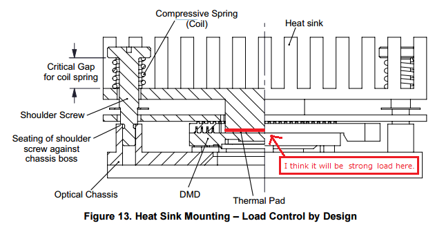
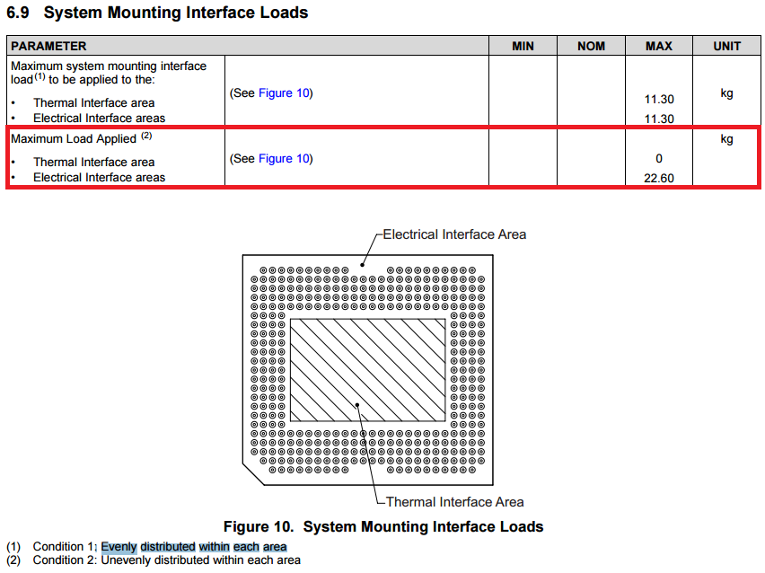
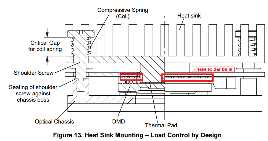
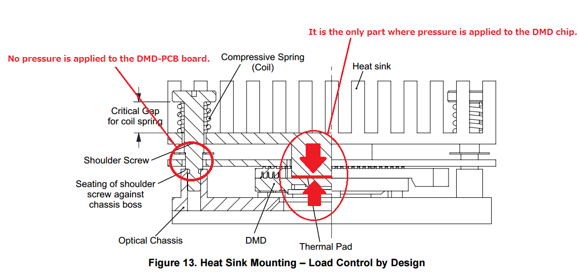
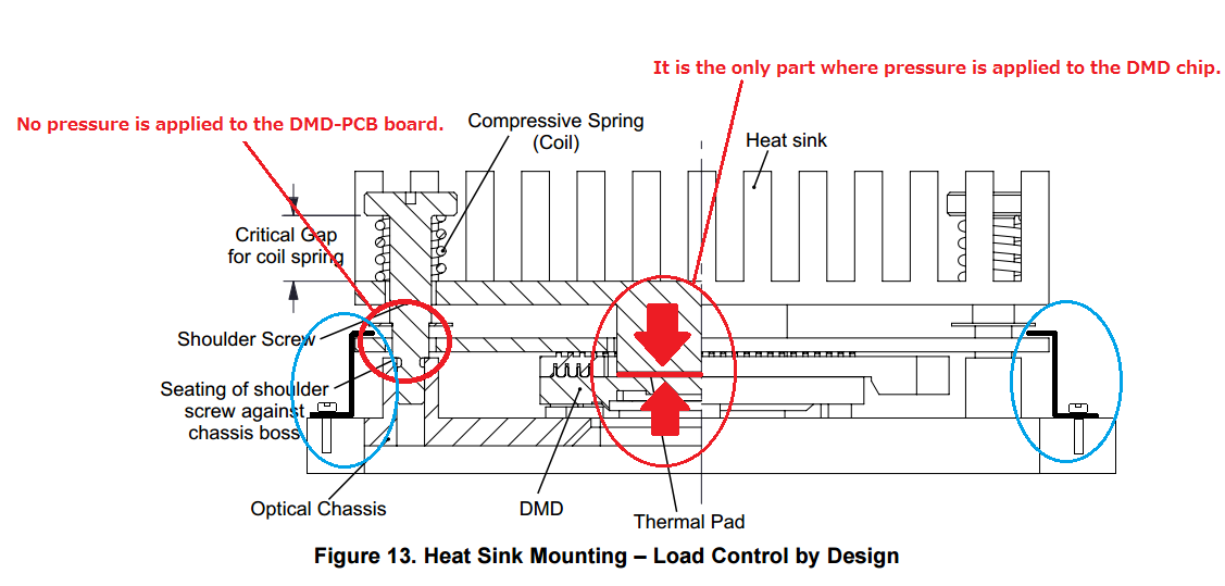
The following documents describe the load of Thermal Interface Area and Electrical Interface Area, Is it possible to install the DMD by equally loading only the Thermal Interface Area?
In other words, is it possible to fix the DMD only with Thermal Interface Area excluded Electrical Interface Area?

Best regards,
H.U

  • Hi H.U,

    I think that because the thermal interface area lies directly beneath the mirror array, we do not recommend loading only the thermal interface area. The datasheet has a described condition where the electrical interface area is loaded by itself, but the condition you are asking about isn't listed.

    Let me confirm this and post back.
    -Paul
  • Hi Paul-san,

    Thank you for your reply. Please forgive me additional questions.

    Q1: It seems that the following DMD mounting concept are described as stressed only the thermal interface area. In the case of this structure, is the load evenly distributed to the electrical interface area?

    Q2: Is TI's system mounting concept considered for the load between DMD socket and DMD-PCB? I am concerned that the solder of DMD soket will crack due to the load that holds the socket and the DMD-PCB.

    Best regards,

    H.U

  • Hello H.U.,

    Regarding Q1:  If the this mounting system is built according to the specification and using springs with the recommended spring constant then the load is designed to apply the correct pressure evenly to the thermal interface area.

    Regarding Q2:  Please note that the opening in the back of the socket and the holes through the DMD board do NOT apply preasure to the socket and its solder mount.

    The DMD board has holes larger than the shoulder screw.  Therefore the heat sink pushes against only the back of the DMD which in turn is pressed up against the optical chassis. 

    Fizix

  • Hello Fizix,

    Regarding Q1: Are you say that only the thermal interface area is pressed? If so, I think that this mounting system can not meet the specifications of the data sheet below.


    Regarding Q2: The mounting system in the figure below, I think that the force to hold down the solder ball of the DMD socket will be added. I want to know the acceptable value of the stress added to this part.


    Best regards,
    H.U

  • Hello H.U:

    It is not required to apply 11.3 kg to the electrical interface area, but up to (max).  You are correct that the DMD board will need to have some mechanism to apply some pressure to the back DMD board that will in turn be pressing against the solder balls and therefore pressing against the electrical interface area.

    I am not understanding why this arrangement will not meet the specification.  If the heat sink is pressing with 11.3 kg and the DMD board with 11.3 kg, the total on the back of the DMD will be 22.6 kg which meets the specification.

    If the explanation above does not clarify the specification, please help me understand why you believe that it will not meet the specification?

    Fizix


  • Hi Fizix,

    I think that the heat sink is pressing against the Thermal Pad and the Thermal Pad is pressing against only the Thermal Interface Area. but it seems that no pressure is applied to press the DMD-PCB board. because, the DMD-PCB board only is prevented displaced laterally at the grounded part with the Shoulder Screw and the Push Nut. So I am wondering how pressure is exerted on the Electrical Interface Area.


    Best regards,
    H.U

  • Hello H.U,

    Your understanding is correct.  No pressure is required against the electrical interface area.  However some kind of physical stop or mount needs to be designed into your system to prevent the DMD board (& socket) from pulling away from the DMD. 

    You can have as little as 0 kg or as much as (but not more than) 11.3 kg pushing on the electrical interface area in your design.

    See the areas circled in blue in the image below.  These show a possible 0 force clamping system.  Such a clamp should actually lightly touch the DMD board sufficiently to keep it in place in the presence of expected vibrations in your application.  I hope this helps.

    Fizix

  • Hello Fizix

    Please let me reconfirm this to make sure.
    Are you say that the DMD can be pressured to only the thermal interface area, NO pressure is required against the electrical interface area?
    I think that I have to put pressure to the electrical interface area rather than the thermal interface area in order to satisfy the requirements of the system mounting interface loads.

    Best regards,
    H.U

  • Hello H.U,

    That is correct NO pressure is required against the electrical interface area but it can handle up to 11.3 kgf.  The loads listed  are the maximum allowable but not required.  The heat sink needss a sufficient load to make good thermal contact with the thermal pad on the DMD, but the electrical interface area does not need any load.

    When you say, " . . . satisfy the requirements of the system mounting interface loads."  Which requirements are you referring to?  It is not the requirements from the DMD data sheet.  If your system requires a load against the electrical interface area, then the DMD data sheet only specifies the maximum load you can apply.  That would be your system specification.

    Fizix

  • Hi Fizix,

    Paul say that "we do not recommend loading only the thermal interface area. ", but you have the opinion that it is no problem.
    Why are different opinions in TI? Which one is correct?

    My customers mount the DMD with the configuration shown in Figure 13 above. They are giving pressure to only the thermal interface area, and the pressure is usually 8kg, even in the part with the maximum load is 11kg.
    However, their system is occurring problem that some of the mirrors should originally be in the OFF state, but these are unintentionally in the ON state.
    It is known that this phenomenon can be improved by decreasing the pressure in the thermal interface area.
    We are concerned that the problem is happening despite meeting your opinion and the requirements of the data sheet.

    Although it seems that the load limit is satisfied, Is there something that is considered to be the cause of that?

    Best regards,
    H.U
  • H.U,

    Now I understand. I am amending his information after consulting with the DMD mechanical team.

    Yes it is possible to load only the thermal interface area.

    I am sorry for any confusion.

    Fizix

  • Hi Fizix,

    Thank you for your reply.
    I understood that it is possible to load only the thermal interface area.
    However, The customer system has problem despite pushing at less than 11.3kg. Please let me know what the possible causes are in regards to that.
    If the problem is not solved, DLP6500 can not be adopted. So, we need your help.

    Best regards,
    H.U

  • Hi H.U,

    What type of problem has the customer's system developed with regard to loading? Does the DMD not stay in place? Is is being damaged by the mounting system? Please provide more detail if you're able.

    Thank you!
    Paul
  • Hi Paul,

    The problem is that some mirrors do not work correctly. The DMD does not shift and it is staying.
    For example, When projecting an image that all mirrors are OFF, only a part of the mirrors will be ON.
    Reducing the pressure in the Thermal Interface area improved the problem.

    Best regards,
    H.U
  • Hello again H.U,

    Is the customer design using a zero insertion force (ZIF) socket or a low insertion force (LIF) socket.

    This sounds like a possible damaged clip inside the socket.  DO you have pictures of the pattern when all of the DMD mirrors are supposed to be off?  This may help diagnose the issue.

    Thanks.

    Fizix

  • Hi Fizix,

    I will ask customer about using socket type and feed back soon.
    I can not post picture to E2E forum because of the confidential request form the customer.
    Please accept a friend request. I will send by e-mail.

    Best regards,
    H.U

  • H.U,

    We completely understand. I have accepted your request.

    Fizix