This thread has been locked.

If you have a related question, please click the "Ask a related question" button in the top right corner. The newly created question will be automatically linked to this question.

DLP3000: MBMC Request Help

Part Number: DLP3000

Hello,

I have the LightCrafter EVM aka LightCrafter 3000.

I need help in writing a specific MBMC request as I'm not sure about the exact parameters of the request. 

So here are the details:

I have 41 patterns to display in sequence.

The colors in the patterns are black and white only, and needs to be displayed in black and white -> Which is why all 3 RGB LEDs are needed? Is the bit depth still 1 bit in this case?

Exposure time would be 333 microseconds if possible, would it be also possible for the trigger period to also be 333 microseconds such that there is no trigger delay?

Thank you very much and looking forward to your advice.

  • Hi Jing Yang Kwek,

    Welcome to the DLP forums and thanks for your question.

    What bit depth are your 41 patterns? If they are binary, that is no problem. The Lightcrafter can only support up to 96 bit planes.

    The Lightcrafter can only drive one LED at a time so to produce a white pattern, you need to cycle through the LEDs. Your exposure and trigger periods should be possible - the best way to test would be to tell me what type of sequence you want and then to try it out.

    Best,
    Paul
  • In the case of cycling through the LEDs to produce a white pattern, the exposure duration specified will be for 1 LED only? In other words, for e.g. if i want the white pattern to be shown for 300 microsends, the exposure duration should be 100 microseconds?
  • That is exactly right.
  • Thanks for replying, Paul. Before getting a MBMC, there's another thing I wanna try. But I'm not sure if I should create a new thread or add on to this thread. Do inform me if you think it's better for the community if I post the question below onto a new thread.

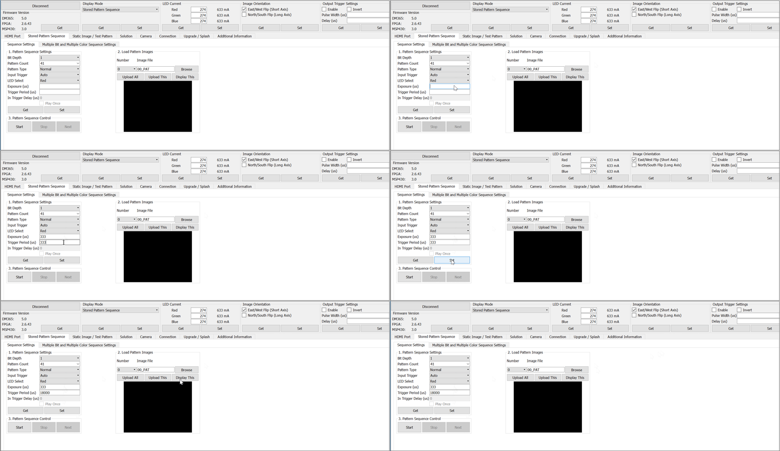
    I'm using the "Stored Pattern Sequence" with the current settings:
    Bit Depth: 1
    Pattern Count: 41
    Pattern Type: Auto
    LED Select: Red
    Exposure: 18000
    Trigger Period: 18330

    For the exposure and trigger period, even if I were to put smaller values and "Set" it. Whenever I "Get", the values will always be set to 18000, and 18330 respectively. I have two questions in this case:

    1) Is 18000, and 18330 the minimum value given bit depth of 1 and pattern count of 41? Is there a way to minimize this further?
    2) The trigger period will always be Exposure + 330 microsends, or 18000 at least. Is this another limit imposed?

    Again, feel free to inform me if you need me to post this question on a new thread. Thank you.
  • I'm surprised that you're seeing a minimum exposure time of 18,000. It should support much lower times for binary patterns. You're using the latest GUI/SW?

    As far as the trigger period being greater than the exposure, there is a limit due to the time to load the DMD. I should correct one of my previous responses to say that there will always be a gap between the exposure and trigger periods.
  • Weird, now I'm able to get the exposure to be 333 microseconds, but the trigger period will still default to 18,000 microseconds when I "Set" a smaller value, and press "Get".
  • Strange. I would recommend restarting the unit and starting the pattern configuration over from scratch. It shouldn't limit you to 18,000us.
  • I've restarted the unit and the issue persists. I've captured a gif of what I did. Maybe you could identify some errors from it. Thanks. 

  • Hello Jing Yang Kwek,
    We were able to replicate your problem. It appears there is a bug when selecting 41 patterns that the trigger period will go to 18000us. However, if you are able to use 40 or 42 patterns for your application the 333us will have a trigger period of 468us. If you are able, try to stick to the predefined pattern counts in the dropdown menu (I noticed 40 and 42 are default options but not 41). If you need exactly 41 patterns let us know!
  • I see. Is it possible to have 41 patterns exactly?
  • We don't see any reason it shouldn't be possible. It is likely a software bug. If 40 or 42 patterns work for you that would be your best bet. If you need 41 we will need more time to investigate and find a solution.
  • What I'm actually trying to do is to imiate what a project has done on the DLP4500. I have the settings file for the DLP4500, would it be okay to advise me based on the content of the .ini settings file?
  • The Lightcrafter 3000 doesn't share the same type of system architecture as the Lightcrafter 4500 so the .ini file doesn't really transfer.

    Can you explain in a little more detail what you're looking for? Maybe we can set up a MBMC sequence.

    -Paul
  • I have 22 patterns. Pattern #00 to Pattern #21. I want to display in such a manner as seen below (A total of 41 sequences). Exposure time & Trigger Period: 333us. I think I'm fine with using 1 LED (Red) for now. 

    Pattern #00
    Pattern #01
    Pattern #02
    Pattern #03
    Pattern #04
    Pattern #05
    Pattern #06
    Pattern #07
    Pattern #08
    Pattern #09
    Pattern #10
    Pattern #11
    Pattern #12
    Pattern #13
    Pattern #14
    Pattern #15
    Pattern #16
    Pattern #17
    Pattern #18
    Pattern #19
    Pattern #20
    Pattern #21
    Pattern #21
    Pattern #21
    Pattern #21
    Pattern #21
    Pattern #21
    Pattern #21
    Pattern #21
    Pattern #21
    Pattern #21
    Pattern #21
    Pattern #21
    Pattern #21
    Pattern #21
    Pattern #21
    Pattern #21
    Pattern #21
    Pattern #21
    Pattern #21
    Pattern #21

    To add on, a portion of the .ini file for DLP4500 is as seen below:

    DEFAULT.PATTERNCONFIG.PAT_EXPOSURE 0x14d ; 
    DEFAULT.PATTERNCONFIG.PAT_PERIOD 0x14d ;
    DEFAULT.PATTERNCONFIG.PAT_MODE 0x3 ;
    DEFAULT.PATTERNCONFIG.TRIG_MODE 0x1 ;

    Am I heading in the right direction for this?

  • Not really. I think there is still some confusion. If you only have one color needed, you don't need an MBMC sequence.

    None of the Lightcrafter 4500 features transfer back to the Lightcrafter 3000. What exactly are you looking for when you set the pattern mode and trigger mode? If you can describe your system behavior or the behavior you desire, I can tell you if it's possible.

    As addressed by Kyle above, 41 patterns has an issue with your desired exposure time. For the time being, try a pattern sequence with just 40 patterns and see if it works as expected. Have you followed the DLPLIGHTCRAFTER user's guide instructions on setting up a pattern sequence?

    -Paul
  • Currently, I'm trying to use a pattern sequence of 42 patterns. I'm having a photodiode, programmed in C to detect 1 pixel for each pattern in the whole 42 sequence so as to determine its location in the projected area. Right now, it's not working as expected, one issue that I could think of is that it didn't obtain the pixel values correctly due to the extra 135us delay (trigger period 468 us - exposure time 333 us).

    Is this resolvable?
  • To add on, if I were to need a pixel to be approx 1.15mm and 1.12mm (horizontal x vertical). How do I do the calculations to achieve so?
  • What type of timing are you using with the photodiode to capture the pixel? You're not going to be able to get around the load time of the DMD, so you'll need to adjust how you trigger your measurement.

    For the pixel size calculation, I think the easiest thing to do is:
    * Assume a pixel size of 1.15mm by 1.15 square. Because of the diamond orientation of the DMD, you are really concerned with the length of the diagonal across the square pixel, which is 1.15*sqrt(2) = 1.62mm
    * There are 608 diamond pixels across the top edge of the DMD.
    * Multiply 608*1.62mm to get the total width of horizontal projected image, which is ~985mm.
    * Move the projector position until the measured length of the top edge is 985mm and your pixel size should be ~1.15mm by 1.15mm

    -Paul
  • Hi Paul, 

    Thanks for the calculations. Do you have an illustration to help better visualize this calculation? So I can do other calculations on my own in the future.

  • No, but I can generalize the above math for you:

    (Desired projected square pixel edge length)*sqrt(2)*608 = Total Horizontal Projected Image Dimension
    or
    (Desired projected spot diameter)*608 = Total Horizontal Projected Image Dimension

    Both the pixel edge length or diameter and the horizontal projected image size will have the same units.

    -Paul
  • One issue I have now is that to produce a project whereby the top edge is 985mm, I have to hold it at about 1.6m away. The brightness on the surface is affected greatly by this distance, and it makes it less detectable by the photodiodes. In order to increase the brightness, I would have to adjust the LED current? But to do so without additional cooling would be dangerous?
  • You could brighten the LEDs by increasing the current. How much you can increase without cooling is covered in the user's guide.

    Another option would be to simply increase the number of pixels you use to create the projected spot. If you create a square on your bitmap which are you loading to the Lightcrafter which is more than a single pixel, you'll be able to put the projector closer and get more brightness. The image I show below illustrates this mapping. The more pixels across you use to create your spot, the closer you can put the projector, therefore increasing your brightness.

    Now, the math becomes:

    (desired spot diameter) / (width of spot in pixels) * 608 = Horizontal Projected Dimension

    I hope this image and the calculation make sense.

    Best,

    Paul

  • I'll try and work with that. Just a quick question, is the DLP4500 capable of having no delay between their exposure time and the trigger period?
  • The Lightcrafter 4500 can have exposures as small as 231us and the exposure time / trigger period can be the same.

    -Paul
  • I see. Do you have the formula to calculate for the vertical projected area?
  • I have not verified this, but I believe that it would be:

    For a spot which is single pixel --> (radius of desired spot size)*684 = Vertical Projected Dimension (VPD)

    For a spot which is multiple pixels --> (diameter of desired sport size) / (number of vertical pixels in orthogonal image) * 684 = VPD

    For clarity, when I say the number of vertical pixels in the orthogonal image, I mean how many pixels tall is your "spot" in the input image. As an example, look at the 2x2 spot in the image above. It consists of 3 pixels in the vertical dimension.

    Hope that is clear.

    -Paul

  • Thanks for the help. I've sorted things out. The major issue was with the patterns that I loaded in!