This thread has been locked.

If you have a related question, please click the "Ask a related question" button in the top right corner. The newly created question will be automatically linked to this question.

DLPLCR6500EVM: J20 Trigger Connector Melting

Part Number: DLPLCR6500EVM

To whoever can answer this question,

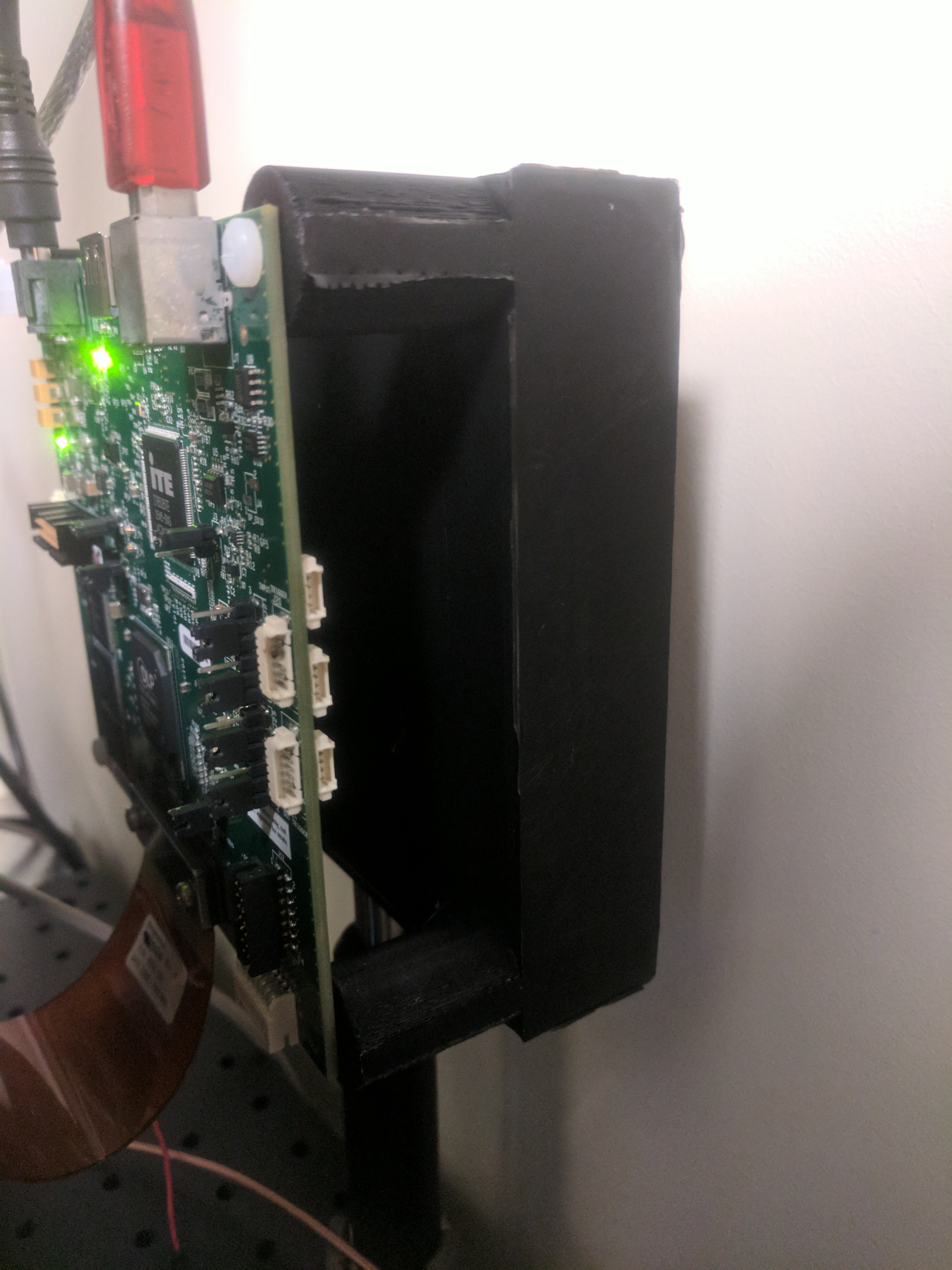
We are trying to trigger our DLP Lightcrafter 6500 DMD by input trigger J20 as described in the manual. We had this working a couple of weeks ago. However, recently the connector to J20 ( Digi Key part number WM1724-ND) has been melting immediately after it is plugged in to J20. The Digi Key connector has six wires that connect to the six pins on J20 but it is not connected to the teensy microcontroller we are using for this project, when it begins to melt. The J20 input has sustained some damage that can be seen in the attached photo. 

Any answers to the following questions would be appreciated.

Why is the melting occurring? Is it a short?

 Is the J20 beyond repair?

Is there another way to trigger a pattern change? J24 perhaps? I've looked through the manual and their doesn't appear to be an alternative way to trigger it?

What are my replacement options? Can I just replace J20? Or do I need to replace the whole device?

Thanks for any help,

Nathaniel

  • Hello Nathaniel,

    Welcome to the DLP section of the TI-E2E Community.

    The following is based on feedback from one of our engineers familiar with this system:

    Below is the circuit surrounding J20 and the trigger input.  In your picture you have jumpers on J19 and J21 which select the on-board 3.3V supply for devices U25 and U27.  In this mode of operation, there should not be any wires coming into pins 1 and 4 of J20 as this would imply a shorting of this on-board 3.3V supply to whatever is at the other end of those wires.  It is okay to leave the pins unconnected. 

    If these were connected to other current sinks or different potentials, then this current flow could be the cause of the connector melting.   Please note that the board will also be expecting input voltage levels of 0-3.3V on J20-2 and J20-5, and that J20-3 and J20-6 should be connected to your ground reference on your micro-controller board.

    Please let us know if this helps.

    Fizix

  • Nathaniel,

    I forgot to answer your question about the connector.

    You can replace the connector, but it is not certain that the board traces have not been damaged.  This is the correct connector for triggering, but there does seem to be some kind of short somewhere.  Please be sure that the jumper shown is in the correct position for your use case.

    Fizix

  • Thanks for your help, 

    I'm still having some issues with melting. I do want the jumper to be at 3.3V so that shouldn't be the issue. Before I had all six pins in use as follows. Pin 1 was to the power bus of my Arduino. 2 was an Arduino pin that was always high. 3 was to the ground of the Arduino. 4 was to the power. 5 was to a Arudino pin that would send a pulse when we wanted to trigger the device to change patterns. 6 was to the ground. 

    I've since removed the pins 1 and 4 as you suggested ( I didn't realize that the trigger was powered by the 3.3 V of the device), but I'm still getting smoke after about 3-4 minutes of turning the LightCrafter6500 on. Do you have any more suggestions on how to fix the problem? Also is there a reliable way to check if the board traces have been damaged?

    Thanks again,

    Nathaniel

  • Hello Nathaniel,

    Why are you holdinging Pin 2 (TRIG1_IN_CON) high since you are using Pin 5 (TRIG2_IN_CON).

    You need a stereoscope to inspect the traces as best as possible.  Also check that you have J21 with pins 1&2 jumpered (i.e. 3.3 V).

    Beyond that, use the mini schematic above, to make sure none of the traces are now shorted.

    Fizix

  • I'm holding pin 2 high because it is my understanding that pin 5 will not trigger unless pin 2 is high. Since I want pin 5 to trigger when it is supposed to, I keep pin 2 high so that pin 5 is ready to trigger all the time.

    I've come to the conclusion that the board needs to be replaced. What is the best way to go about this? Should I just order a new one? Or should I go through some other procedure and get some kind of discount since I'm replacing it?

    Thanks,
    Nathaniel
  • Nathaniel,

    Before you do that you might try ordering U26 (SN74LVC1G17DBV) that is connected to pin 2 on the board and replace it.

    I think they are about 50 cents from distribution such as Arrow, Avnet, or Digikey.

    You may also want to replace U25 (SN74AVC1T45DRLR) for about 70 cents.

    This is worth a quick try.

    Fizix
  • Thanks again for your help,

    I've ordered the parts you mentioned, In the meantime can I get a replacement cost estimate in case this does not fix the problem.

    Nathaniel