This thread has been locked.

If you have a related question, please click the "Ask a related question" button in the top right corner. The newly created question will be automatically linked to this question.

DLP4500: dlplcr4500

Part Number: DLP4500
Other Parts Discussed in Thread: DLPLCR4500EVM, TIDA-00254

Hi

I am working on DLPLCR4500evm for creating accurate 3d point cloud. at the very first steps of using the TI proposed application for driving the DLP evm and PG camera, i have a problem for calibrating the projector.

The problem is when i try to perform the projector calibration procedure , the projector does not project the calibration board. in this step i have the live video and when i hit the space bar, i receive an error saying projector calibration board not found.the error is shown below:

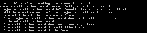
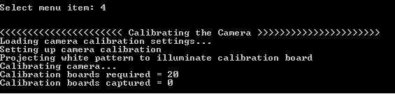
also i should say that i can complete the camera calibration process. but at the beginning the projector does not project any white pattern to illuminate the calibration board.


thank you for your help

  • Hi Hadi,

    Sorry that you're having difficulty with the design! After reading your question, the first issue that I can potentially see is that you're using the wrong connection for the camera trigger. If you are not using the right trigger connector on the LCr4500, you won't see the white illumination during camera calibration as expected. Can you attach a picture of your setup?

    Once we work through that issue, we can tackle the next one.

    Best,

    Paul

  • Hi,

    thank you for your replay. i checked the trigger setup. i didn't notice any mismatch in my setup compared to what i saw in the documents mentioning the correct way of trigger connection in LCR4500. the fallowing picture shows that how i did that. as you see i connected the pin #2 and #3 to of the trigger port to the pin#3 and #5 of the pg camera port. this way i get some colorful pattern in step 4 (camera calibration). i tried other pin connections and i got nothing. in all of the configurations there is no pattern projected to the calibration board in step 5 (projector calibration).

    thank you for your helps.

    regards

    hadi

  • Looks like you're using the right connector, that's good. Did you perform the "prepare projector" step and make sure that the correct firmware is loaded onto the device?

    -Paul
  • hello again;
    my problem haven't been solved yet, paul.
    Do you think maybe it should be related to USB 3 port?
    because I am using USB 3 port of my laptop and i don't know it has a suitable interface card or not?
    As you said, I performed prepare projector step and loaded correct firmware "DLPR350PROM_v3.1.0.bin" but the problem didn't solve :(
    Also when I set up calibration_camera in config folder to produce 7*10 chessboard it produce 8*11 chessboard.do you think it may be related to this issue?I did step 4 completely and reprojection error is 0.48 but step 5 is still as it was last 2 week.
    best
  • Hi Hadi,

    Sorry that you're still having issues.

    Here are a couple things you can do for me so that I can better help you out:
    * Can you send me a picture of your overall setup? I'd like to see the screen, projector, and camera all in one picture.
    * Look at jumper J13 and make sure it is in place. Try moving it to the 3.3V position instead of the 1.8V position and see if that solves your problem.
    * What type of camera are you using?

    Best,
    Paul
  • Hi paul.

    I really enjoy when read your complete answers and paying attention for solving my problem.

    In this message, I want to explain different parts of the system completely and the solutions that have been made to solve the problem  but the problem remains:(

    for the first step I want to show you dlp4500evm top surface and please check it for me is there any jumper that i don't place it?

    it should be noted, in this condition D4 blinking and fan is on.

    also I am using FL3-U3-32S2M-CS  point gray but the connections between evm and camera will be shown in the next steps.

    As I said before, I performed the first four step completely and the camera.xml has been generated although in step 4 the white pattern does not illuminate from projector but all of 20 pictures were saved and camera.xml was generated. you said me before, this issue may cause for connections between camera and evm and triggers which haven't been sent from camera to evm. also step 5 doesn't have been performed because of this issue ,and trigger signals should be sent to trigger input connector from camera to evm.

    but connections between camera and evm:

    first I connect camera cable to to j11 as i show it in below picture. I think the pin numbers of j11 start from left to right so pin 2 of this connector should be attached to red  wire of camera cable and pin 3 of j11 should be attached to brown wire. Also i tried it vice versa which means I suppose pin numbers start form right to left but still doesn't work:( also i tried input trigger 2 which is pin 5 of j11 but still doesn't work.

    Also I use scope  to check the trigger signals are generated or not? when i run the application the triggers signals generated by camera as you see in below picture and when I change the frame rate from camera.config the frequency of pulses will be changed correctly and the voltage level of trigger pulses are about 3v. but the interesting point is here when I connect pin 2 of j11 to red wire and check the signal from scope Simultaneously the trigger signals are destroyed(0v) in this condition I cant see camera trigger signal between red and brown wire but I can see it between red wire of camera cable and pin3 of j11.

    in previous message that i received from you, you mentioned check jumper number 13 and when I searched it from dlpu011f,it is related to external trigger output connector while in the schematic file shows we should connect cammera to j11  nevertheless after that I place the camera cable to this connector and in  each position(left or right. but still doesn't work.

    Also I check pattern sequence mode from gui and all of the pattern are saved in flash and i can see illumination of this but without camera and triggers so the firmware file is uploaded correctly.

  • Thank you Hadi for the detailed information and background. Let's work through things one at a time and make sure everything is okay.

    The first thing that I noticed is that your camera is a rolling shutter camera, which has to be accounted for by the software. Can you please look at {installed directory}\TIDA-00254_3D_Scanner_LCr4500-2.0\LCr4500_3D_Scanner_Application_v2\config\config_camera.txt?

    You should set PG_FLYCAP_PARAMETERS_PIXEL_FORMAT = MONO8.

    I would also recommend slowing down your exposure and frame rate to the following:
    PG_FLYCAP_PARAMETERS_SHUTTER_EXPOSURE_MS = 66
    PG_FLYCAP_PARAMETERS_FRAME_RATE_HZ = 15

    Then, in config_projector.txt (found in same folder as above), set the following:
    DLP_PLATFORM_PARAMETERS_SEQUENCE_EXPOSURE_US = 16666
    DLP_PLATFORM_PARAMETERS_SEQUENCE_PERIOD_US = 16666

    What we are doing here is slowing everything down to see if that helps account for the rolling shutter behavior.

    I looked at your board and all the connections and jumpers look correct, so that eliminates a number of possible issues.

    Let me know if changing those settings helps this work.

    Best,
    Paul
  • thanks for quick answer paul,
    unfortunately, I set them before to mono8 and decrease DLP_PLATFORM even below that these amounts but still doesn't work:( . now i set them to numbers that you said but there was no change :(
    is it possible the wrong connections damaged board?
    what do you offer me to the next step for solving the issue?
  • Next step is to make sure the triggers are correct. Do you know if your camera outputs a positive or negative trigger? You can play with those settings in the same files that I pointed out. Fully investigate your camera and understand how trigger signals are generated (voltage and polarity).

    Best,
    Paul
  • Hello again paul,
    I investigated all of the solutions that exist. I'm really confused which is the next step. I played with all the cammera and projector setting in config files. but the biggest problem is here, I should change the trigger source in config.projector.txt in internal one, because at least in this situation the projector project some patterns and white pattern in the correct position,however when I changed it to external there aren't any projected pattern or white pattern in each position on the surface. this change destroy each step of scanning.
    if, it is possible I ask you,tomorrow whe have a skype call please to show you all the obstacles and you see all the settings.
    The employer has put a lot of pressure on me to come up with the answer to this part of the project, but unfortunately this part is without the slightest progress.
    thanks alot paul
  • Hello Hadi,

    Paul has moved on to a different group but I will take over supporting you. Please accept my friend request so we can discuss the next steps to move forward.

    Thanks,
    Kyle
  • Hi,

    i wonder that the issue has been solved yet?

    i have the same qustion now.

    Another quetion is that i connect pin2 to the red,and pin3 to the brown one, i'm using the Flea3-u3-13Ym point grey. is that connection right?

    look forward to your early reply.

    Thank you

  • Hello user,

    I believe it might actually be white and brown. However, you would want to check the Point Grey documentation on their cameras. The Lightcrafter 4500 expects the external trigger input from the camera. If you have further questions user feel free to open a new thread so we can properly support you.

    Thanks,
    Kyle
  • Hi,Kyle

    Thanks for you reply.Actually i can only get the picture above for the GPIO of flea3 camera.

    But i'm confused there are only 8 pins,not 9pins just like my camera on my table. Do you mean i should try the white and the brown?

  • If your camera has nine pins you may need to contact the camera manufacture to ensure you can find the correct documentation. I believe you should try it with the white and brown; however, I don't have access to my setup today to confirm. I will look into it and get back to you tomorrow.

    Thanks,
    Kyle
  • Hello user,

    I just confirmed that on my camera (FL3-U3-13Y3M-C) I am using pin 3 (red) and pin 7 (orange). If that doesn't work for you try pin 2 (white) and pin 6 (blue). For that specific camera it does appear one needs to use the opt-isolated cameras.

    Thanks,
    Kyle

  • Hello user,

    I realized I spoke improperly before about the pins I was using. I have updated my response above.

    Thanks,
    Kyle