Part Number: DLP3000
Greetings,
I have been trying to work through the document "Geometric Optics for DLP" (DLPA044) to determine several optics properties of the DLP Lightcrafter light engine, for the purpose of adding lenses after the projector to change the optical output. Essentially what I would like to do is focus the light output from the projector onto a smaller area than it currently throws to.
My problem is that the document gives several calculations relating to the optics, with conflicting results.
For example, to determine the focal length of the modeled thin lens, we can either use the Throw Ratio, or the F-number.
The F-number formula given is F-number = focal length/aperture. Aperture is given in the document as 6 mm for the lcr (I confirmed this loosely by measuring the actual opening of the projection assembly in the light engine). F-number is given in the user manual as 2.2. Therefore, focal length = F-number * aperture = 2.2 * 6 = 13.2 mm.
Using the throw ratio, method, we are give T = (distance from lens to image)/(width of image) = (distance from lens to DMD/active width of DMD). We are also given T = 1.66. Documentation for 0.3" DMD gives active width as 6.5718 mm. Therefore, using T = D/W, D = 1.66 * 6.5718 = 10.9092 mm. This is the distance between modeled lens and DMD.
Then in the next section, we are told to calculate the focal length by using f = 1/(1/do + 1/di) where do = distance to object and di = distance to image. "Since we don't know distance to image used to measure width of DMD, we estimate at 1000mm". Using this, f = 1/(1/10.9092 + 1/1000) = 10.7915 mm. So now the focal length is 10.7915.
The obvious problem here is that the focal lengths don't match. If you refresh on high school physics (or just use this simulator here) you find that putting the object closer to the lens than the focal point produces a virtual image, not useful for projection. Thus, while the 13.2 mm focal length seems more reliable, it is problematic because it implies a longer focal length than distance to object (10.9092mm) as calculated with equally reliable throw ratio.
I assume there is an issue with the thin lens assumption here. This also becomes evident when you try to use real dimensions of the light engine.
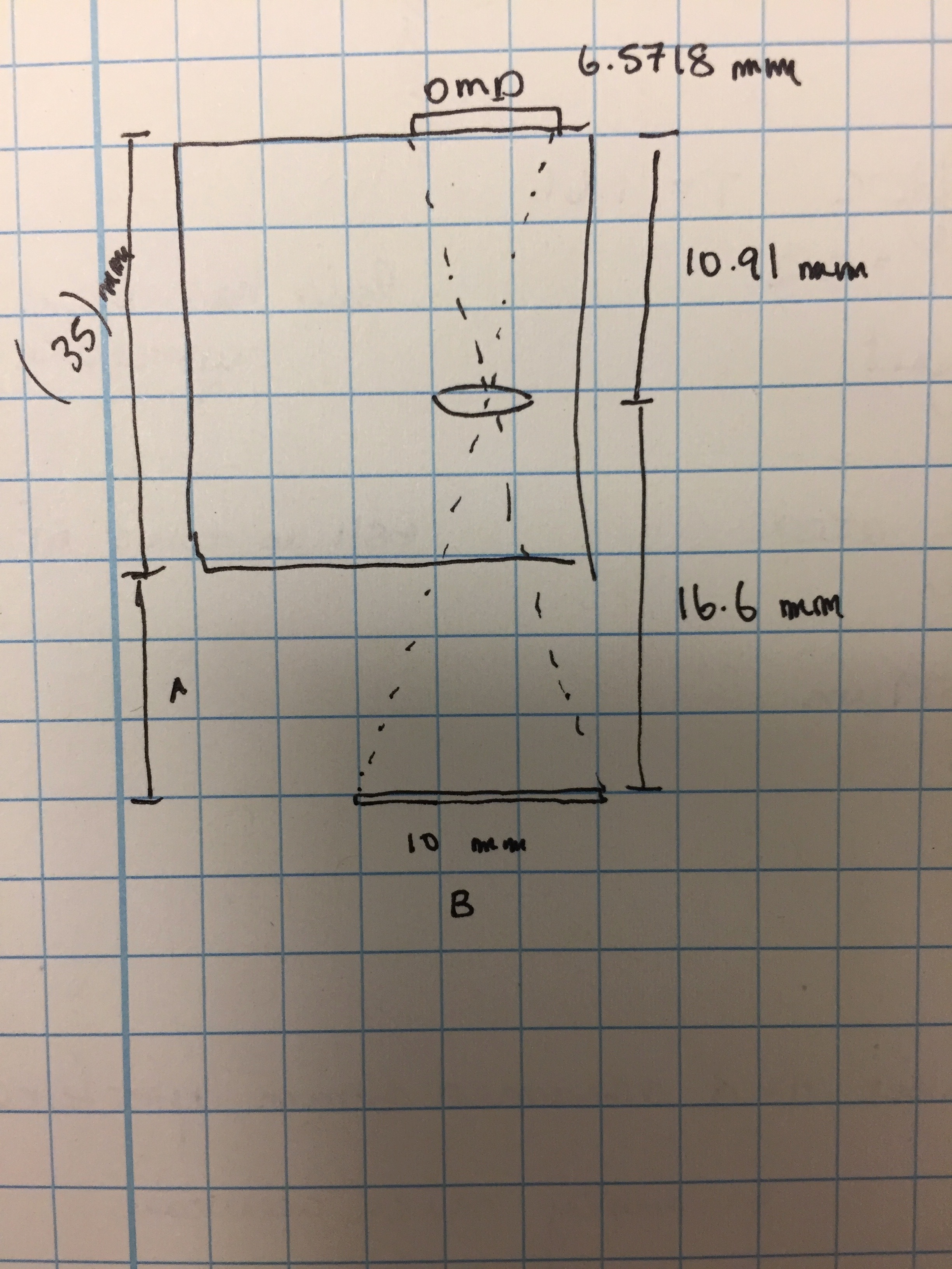
I drew up a quick schematic of the projector and thin lens model. DMD is at top right, projector output is at bottom right.
Using the throw ratio = 1.66, at 16.6 mm away from the lens the image should be 10mm wide. Also given that the DMD is 10.9092 mm away from the lens (this was calculated without making up any numbers), the total distance from DMD to image would be 17.51 mm. However, I physically measured the projector and it is approximately 35mm from DMD to edge of projector (see image above). I also know from experience with the output that the image at 5mm away from the edge of the projector (distance A in image) is less than 15mm wide (width B). Clearly there is a problem with the calculation somewhere, because the size of the light engine itself is greater than my calculated 27.51 mm.
I'm sorry about the long read, here are the questions.
1. Has anyone calculated the focal length (or focal lengths since it is adjustable?) for the DLP light crafter?
2. If not, has anyone followed the instructions in the optics document and gotten the same results as I did?
3. Can anyone explain this calculation issue?
I am going to do some measuring of actual distance from projector to a 10mm wide image (distance A in schematic) to see if it sheds any light on the issue.
Best,
Brice


