


Other Parts Discussed in Thread: DLPDLCR4710EVM-G2
Hello.
We are designing a lithography application using the DMD4710 chip.
We will use the DLPDLCR4710EVM-G2 control board. But we will not use the Young Optics optical engine.
Instead we are designing:
* A 6-layer PCB to mount the DMD4710 chip using the neoconix interposer.
* We will use the same 80pin ribbon (FFC typeA) cable to connect the control PCB to our DMD4710 PCB.
* We have seen in the ti forums that is not mandatory to use the W25Q16JV flash memory so we are not connecting the following terminals to the 104060-8017 Molex connector (on our DMD4710 PCB):
FLASH_PWR
EXT_M_SPI_CLK
EXT_M_SPI_DOUT
EXT_M_SPI_DIN
EXT_M_SPI_CSZ
EXT_S_SPI_CLK
EXT_S_SPI_DOUT
EXT_S_SPI_DIN
EXT_S_SPI_CSZ
I will really appreciate if you can take a look to my schematic. And please tell me if in "general" looks correct.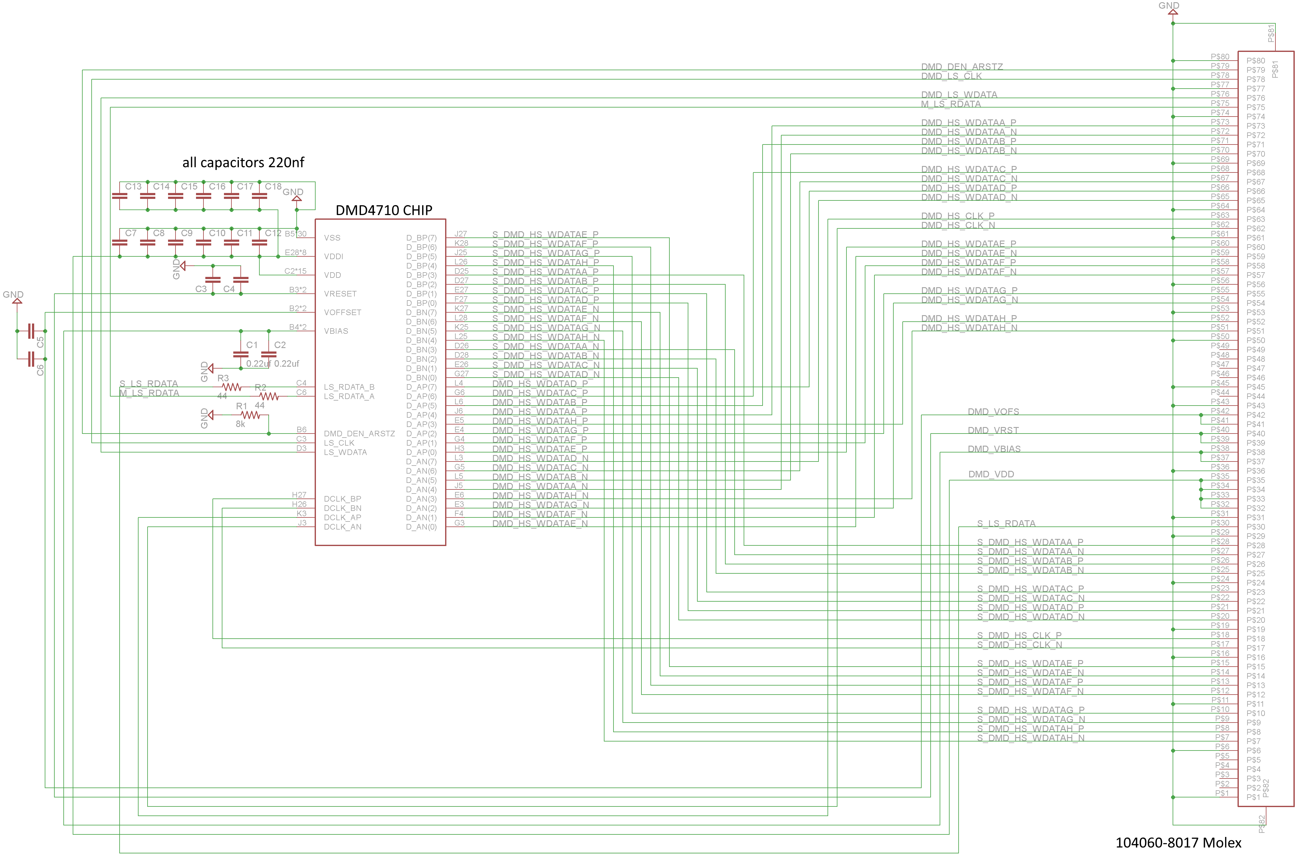
Because I am using a type A ribbon cable (just like young optics does) the pin 1 (on the molex connector) on the control board goes to pin 80 of the dmd pcb.
In the TI layout guidelines mention that the decoupling capacitors are minimum 220-nf. If I use the same recommended capacitors of 440-nf, would it be better?
My PCB design looks like this:

