This thread has been locked.

If you have a related question, please click the "Ask a related question" button in the top right corner. The newly created question will be automatically linked to this question.

DLP4500: Some problem about trigger with DLP4500 LightCrafter

Part Number: DLP4500
Other Parts Discussed in Thread: SN74AVC1T45, DLPC350,

1. What is the difference between Trigger In 1 supply (pin 1) and Trigger In 1 (pin 2)?

Is this similar with this thread? (https://e2e.ti.com/support/dlp/f/94/t/555518?Difference-between-Trigger-Out-2-supply-pin-1-and-Trigger-Out-2-pin-2- )

-->"Trigger In 1 Supply" is essentially the reference voltage for "Trigger In 1" intput trigger. 

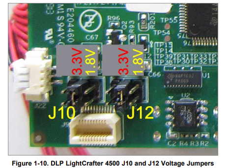
2. In manual, External trigger Input connector: Supports two trigger input signals, each with configurable voltage of 5 V, 3.3 V and 1.8 V through jumpers, J10 and J12.

As following figure, I knew that the configurable voltage of 3.3 V and 1.8 V can be adjusted by making jump across pins 3 to 4 and  pins 5 to 6, respectively.

However, how can I  make the configurable voltage to 5 V?

  • Hello Jia,

    1. Yes, the answer is the same as the previous thread. Trigger in 1 supply is the output reference voltage level. It will be either 3.3V or 1.8V depending upon your jumper selection
    2. Unfortunately you cannot change the voltage level to 5V. This board make use of the SN74AVC1T45 bus transceiver between the DLPC350 output/input triggers and the board connector. The SN74AVC1T45 cannot operate at 5V. If you were to design/modify your own board you could probably add a level shifter to operate at 5V. However, this is not supported on this board.

    Thanks,
    Kyle
  • Hi Kyle,

    Thanks for your reply.

    But I still have some questions:

    1.Why there is output reference voltage level for input trigger signal?Does not the voltage be modulated by the input trigger signal generating from DAQ?

    2.There are three pins(Trigger In 1 supply,Trigger In 1 and Ground) for connecting input trigger signal in DLP4500 LIghtCrafter. However, there only two pins in DAQ. How to connect the pins between the two instruments?

    Sincerely,

    Jia Wei Xu

  • Hi Jia,

    The output reference voltage level for input trigger signal denotes the HIGH level voltage for that trigger in. For example, if you have set the jumper j10 to 3.3V, you will get 3.3V at the EXT_TRIG1_IN_VCC signal. This is for your reference, you need not connect this pin.

    Hope this resolves your query,
    Regards,
    Hirak