This thread has been locked.

If you have a related question, please click the "Ask a related question" button in the top right corner. The newly created question will be automatically linked to this question.

DLP4710: LED & DMD is blinking

Part Number: DLP4710
Other Parts Discussed in Thread: DLPC3439, TFP401

Hello!

I designed my own board with DLP4710 & DLPC3439 which is almost  the same with the DLP4710 EVM board.

The only thing that I changed is HDMI IC. 

The HDMI chip that I mounted on my board is TFP401.

I can turn on the DMD and adjust the intensity of LED.

There is no problem on I2C communication between USB and DLPC3439.

And I set the DLPC3439 to display a built in image.

But the LED and DMD is blinking every one second.

I have a question.

If the impedance between DMD and DLPC3439 is not matched , can it make the system unstable?

Please, answer me about this question.

Regards

Yun-Seok Cho

  • Hi Cho,

    Yes if impedance doesn't match, it can make system unstable.

    You also need to check all your tracks also, they should match with the Datasheet specifications.

    If you want, we can help to review your schematic.

    Thanks,
    Navneet
  • Hello!

    First of all, I appreciate for your answer.

    There was an error on my code for MSP430.

    After fix the error, it doesn't blinking any more.

    In order to verify the code, i downloaded it to my EVM and test it.

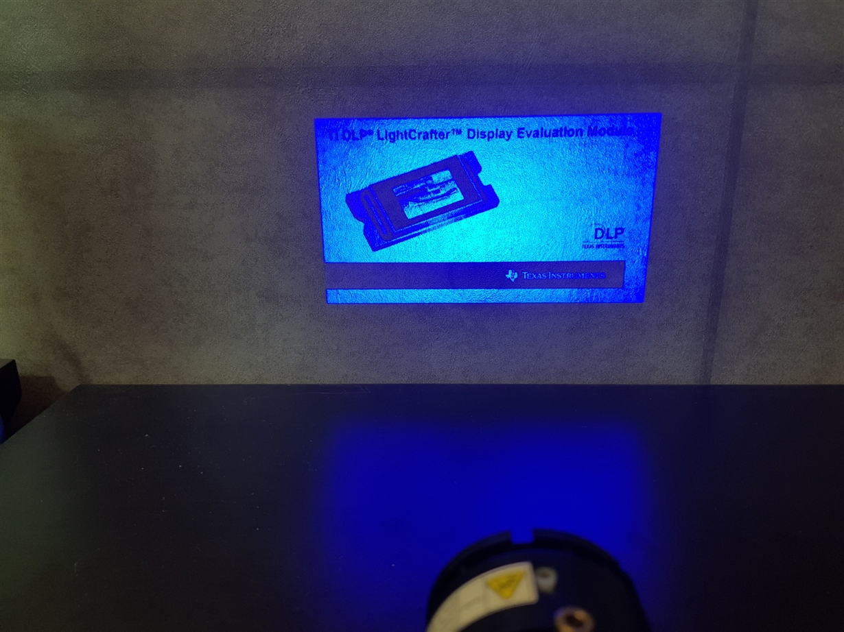
    As like the below first picture, the EVM displayed a good default image.

    And  I also download it to my own PCB and test it.

    But it displayed a different image from the EVM's.

    The image is the second one.

    As you can see the picture, it  shows just vertical lines.

    I checked all of signals between DMD and DLPC3439 but It looks good.

    In this case, what do I first have to check?

    Do I still need to suspect  the impedance matching between DMD and DLPC3439 ?

    Regards

    Yun-Seok Cho

  • Hi Cho,

    It's nice that you figured out your issue and fixed it at your end.

    Have you checked which DMD pin mapping option you used ? Looks like it may be DMD pin configuration error. Check 8.3.10 point in

    www.ti.com/.../dlpc3439.pdf


    For more understanding you can share your schematic to me. I am adding you on e2e friends, please feel free to share any document there.


    Thanks,
    Navneet
  • Hi!

    I'm still struggling with the same problem.

    The pin map looks fine.

    If then, what kind of condition does it show only vertical lines under?

    I think that the impedance between DMD and DLPC3439 perfectly matched.

    If there is no problem on the pin map of connector, i have to move my focus on the other.

    Could you tell me what do I have to concentrate on?

    if you let me know your email address, I can send schematic file and MSP430 code.

    Regards

    Yun-Seok Cho

  • Hi Cho,

    I added you on e2e as friend, please accept the request and share the document there.

    If i would be at your place then i would check following things :

    1. Is Schematic is correct, Is it matched with TI reference design. Did i follow the datasheet and app note recommendation for traces and pullup/ pulldown and other component.

    2. Is Pin mapping is correct, which firmware i am using. Is this firmware supports my selected pin mapping . Like if i am using pin mapping option
    3, Does firmware supports option 3 or is it option 2.

    You can also proceed in this direction, and in parallel i will review your schematic.

    I am busy with some stuff so it may take some time, i will let you know when it get finished.

    I recommend you to check the options i suggested.

    Thanks,
    Navneet
  • Dear Navneet,

    The below table is my pin map between DLPC3439 and DMD.

    Could you please check if I am using a correct version of ASIC or not?

    The ASIC is working well with EVM.

    If I'm using a wrong ASIC, Could you please supply correct one?

    Regards

    Yun-Seok Cho

  • Hi Cho,

    As Navneet mentioned, this issue might be caused by incorrect pin mapping.

    You have provided two pin mapping tables, can you clarify which one is for the master ASIC and which one for slave ASIC?

    The table on the right must be the mapping for the master ASIC while the one on the left for the slave ASIC.

    Can you confirm that this is the case with your system?

    Please refer to this table from page 7 of the reference design schematic:

    Regards

    Azad

  • Dear Azad,

    In my case, the left table is for the master DLPC3439 and the right one is for the slave DLPC3439.

    After Navneet mentioned about firmware, I got to know that the pin map has been switched each other.

    Then, do I have to make new board?

    Or, can we fix this problem with just replacing a firmware of DLPC3439?

    Thanks!

    Regards

    Yun-Seok Cho

    .

  • Hello Yun-Seok Cho,

    We should be able to get you new firmware. It may take a couple of days to create the new firmware, but please accept my friend request on E2E for me to share with you.

    Thanks,
    Kyle
  • Dear Kyle,


    Thank you!

    When you create a new firmware, please consider my below request.

    I'm not going to use red and blue LED. I 'm going to use only green LED.
    Even I plug only green LED, I want to make it working.

    I hope you accept my request.

    Thanks!

    Regards
    Yun-Seok Cho
  • Hello Yun-Seok Cho,

    I have sent you a link via a direct message. Please let me know if the new software works.

    Thanks,
    Kyle
  • Dear Kyle,


    I received your email by private account.
    But I can't find out the link on your email.
    Could you please send me email including the link?

    Thanks!

    Regards
    Yun-Seok Cho
  • Hello Yun-Seok Cho,

    Please see my direct message reply. Feel free to reply directly to the message if you are still having issues with the link.

    Thanks,
    Kyle