This thread has been locked.

If you have a related question, please click the "Ask a related question" button in the top right corner. The newly created question will be automatically linked to this question.

DLPC900: Proper flow for I2C control in Video Pattern Mode

Part Number: DLPC900

I am writing a Python I2C driver for this product. We are using Video Pattern mode to grab images from an HDMI input and display them in one color. We have an LED attached to the blue channel of the DLPC900, and it is my understanding that I can make the sequencer run the LED enables for a set exposure time as referenced in 2.4.4.3.4 "Pattern Display LUT Definition" in the programmers guide. 

I want the sequencer to control the LED but can't seem to get it working. 

Here is what I am doing so far: 

1) Power up HDMI input - Write 0 to address 0x8C 

2) Set port and clock configuration - Write 0 to address 0x83

3) Set video display mode to video pattern - Write 3 to address 0xE9

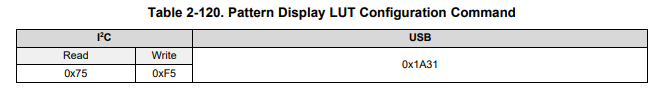
4) Configure pattern display LUT - 1 pattern, repeat = 1

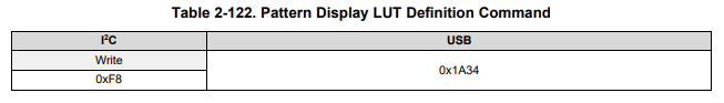
5) Define pattern display LUT - 1,000,000 us exposure, color=4 (blue LED), 

6) Start sequence - Write 2 to address 0xE5

It is my understanding that I should see my image appear for 1 second and then disappear. Am I missing something here? I don't see anything when I do this. 

I can see my image appear and disappear when I write 4 and 0 to address 0x90, to manually enable and disable the LED, and I am getting system and hardware status 1 indicating no errors, I have no error code, and a main status of 26 which indicates the sequencer is running and I have proper video. 

What could I be missing? We follow this approach in another device using the DLPC900 and it works fine, but we turn the LEDs on and off manually instead of giving the sequencer power to do it. 

  • Hi Matthew,

    Welcome to DLP section of TI E2E community. Did you try sending Command 5 before command 4? Expected sequence Pattern display LUT info before
    PAT config.

    -ykc
  • That's what we do for our other device and it works. I tried that first on this new one and it doesn't appear to work, nor does the order I posted.

    In the programmer's guide I see this: 

    This makes me think I should do the configuration first, and then the definition. You are confirming it is in fact the other way around, correct?  

  • To be more clear, here are the two commands in question:

    On my first attempt, I had them in the order you mentioned now, I did the definition first then the configuration. The programmers guide appears to suggest the configuration should come first (see snippet in previous reply). I have tried both ways without success. Which one is correct? 

  • Hi Matthew,

    This is a mistake in programmer's guide. Correct sequence is to send LUT Definitions before LUT configuration. See Section 5.1 of Programmer's Guide for example.
    Also you can see Section 3.6.4 of User Guide for directions on how to use GUI to set video pattern mode. GUI has a batch file page that can record commands sent so that you can see what commands need to be sent for video pattern mode.

    Here is a command list I ran from GUI for video pattern mode
    DISP_MODE : 0x00 // Video mode
    VIDEO_CONT_SEL : 0x01 // Enable HDMI
    DISP_MODE : 0x02 // Video Pattern mode
    MBOX_DATA : 0x00 0x00 0xBF 0x04 0x00 0xA3 0x00 0x00 0x00 0x00 0x00 0x00 // Pattern 0 definition
    MBOX_DATA : 0x01 0x00 0xBF 0x04 0x00 0x13 0x00 0x00 0x00 0x00 0x00 0x40 // Pattern 1 definition
    MBOX_DATA : 0x02 0x00 0xBF 0x04 0x00 0x43 0x00 0x00 0x00 0x00 0x00 0x80 // Pattern 2 definition
    PAT_CONFIG : 0x03 0x00 0x00 0x00 0x00 0x00 // LUT Config
    PAT_START_STOP : 0x02 // Start

    -ykc
  • I think what you sequence missing is External Source is not locked. First go to video mode , enable hdmi or port clock settings then wait for source to lock. Status has bit that state external source is locked or not. Then go to video pattern mode.

    -ykc
  • I want the sequencer to control the LED, so I write 0x8 to address 0x90, is that correct? Otherwise, I have to manually turn it on and off? 

    After defining the pattern and LUT, when I start the pattern, does the DLPC900 grab the current video frame, position the mirrors, and then turn the LED on and then off for the specified exposure time? Or does the vsync field in the pattern definition mean it will wait for the next vsync signal it sees to start the pattern?

    I still seem to be missing something here, as I have checked my video feed and it is locked and valid, and I can see the images I am supplying when I hook it to a monitor. Following the same steps you mentioned, after I set display mode, right before I get to defining patterns and then the LUT, I get a main status of 0b11000 meaning the DMD micromirrors are not parked, the Sequencer is stopped, Video is running (Normal frame change), External source is locked, and Port 1 syncs are valid. The hardware and system status are both 1, indicating no error. Then I just have to do pattern and LUT definition and start the sequence, correct?

  • 1. Yes 0x8 is correct settings. This is default settings. You don't need manual on/off.
    2. It is synced to Vsync.
    3. Yes. Once external source is locked.

    DISP_MODE : 0x02 // Video Pattern mode
    MBOX_DATA : 0x00 0x00 0xBF 0x04 0x00 0xA3 0x00 0x00 0x00 0x00 0x00 0x00 // Pattern 0 definition
    MBOX_DATA : 0x01 0x00 0xBF 0x04 0x00 0x13 0x00 0x00 0x00 0x00 0x00 0x40 // Pattern 1 definition
    MBOX_DATA : 0x02 0x00 0xBF 0x04 0x00 0x43 0x00 0x00 0x00 0x00 0x00 0x80 // Pattern 2 definition
    PAT_CONFIG : 0x03 0x00 0x00 0x00 0x00 0x00 // LUT Config
    PAT_START_STOP : 0x02 // Start
  • So we're actually running the DPLC900 off a Raspberry Pi with a custom python driver that uses the I2C commands. We have two more light engines that also use the DLPC900 that we control in this way and it works well. I decided to replicate your tests and install the windows software to see if there could be a problem in our system. 

    I installed the software, and after startup I set the DLPC900 to normal video mode and I appear to have good status on everything, including video lock on the HDMI port: 

    As soon as it starts up, this is the image I'm getting (below). Even in normal video mode when I switch the images, I don't see any change on the output of the light engine. I always get the same white square that shows up on startup. 

    Do you see anything immediately wrong with this approach? I think I'm doing all the I2C stuff correctly in our other driver, but it is giving us the same result as this test with the Windows software. I also tried replicating your batch commands in the batch mode section and was unable to get that to work either. 

  • Hi Matthew,

    First you have to get it working on video mode itself. Just try connecting a PC video output to hdmi first and see if that is working.
    What is the video frame rate?

    -ykc
  • Hi Matthew,

    Haven't heard back from you. Were you able to fix the problem?

    -ykc
  • Hi Matthew – I haven’t heard back from you, I’m assuming you were able to resolve your issue. If not, just post a reply below (or create a new thread if the thread has locked due to time-out) .

    -ykc
  • When I run the DMD from the TI software from a windows machine via USB, normal video mode works. I'm trying to run it now from a raspberry pi via I2C. I power up and read all the status registers, and I get

    System status: 1  Hardware status: 1   Main status: 26    Error code: 0

    From what I understand, this means everything is working properly and I'm locked on source 1 with valid syncs. So everything looks good. I then set to normal video mode, and I get the same values from all the registers but I get no image. At this point from the windows software, it works. 

    I decided to try to figure out how your windows driver was doing things so I monitored the packets being sent back and forth over USB and it looks like your windows driver queries status, sets power mode, and then sets video mode. After that it appears to read the firmware version and run some batch file.

    I decided to try to set the power mode on startup to normal by writing 0 to 0x87, but when I do this I get error #4 (incompatible DMD/controller) and then subsequent reads of the hardware status give back 2 (incompatible DMD/controller). 

    I think the windows stuff works because there is something else the windows driver does during initialization. How do I properly initialize the system, step by step? Section 4.3 of the programmer's guide says this shouldn't be necessary, but I see the USB driver running something else to set it up. 

  • Upon further inspection of the commands sent from the windows driver, I have confirmed it only sets the video mode.

    When I run the device without usb or i2c connected, it starts up into normal video mode without trouble. As soon as I connect the i2c and start it up, nothing happens.

    It appears that just connecting i2c (and not even sending any commands) somehow disables the auto power up configuration that happens otherwise.

    What I need to know is the sequence of commands that are auto-configured on power up so I can replicate them with i2c.

    Thanks,
    Matthew
  • Hi Matthew,

    Default firmware has prestored patterns and it run a batch file. But you can clear those and create new firmware from firmware tab in GUI.

    This firmware by default runs in video mode and there is no power up command.

    PFA this firmware. I checked this firmware with i2c master connected before startup case and after startup case. Both cases video mode starts with blue screen.

    Please check if this is working for you. If not then please use scope to monitor i2c scl and sda lines.

    dlp6500_12212018113148_firmwareimg.zip

    -ykc

  • I flashed this firmware as you requested, and now not even normal video mode works. 

    I start up to a solid image now, but it will not lock to the video source anymore. I get several errors now: 

    Sequencer error (bit 7 of the hardware status is set) and I get Sequencer Abort Status Flag (bit 6 of hardware status is set) on normal video mode, just starting up from the windows software. I never get video lock. 

    From i2c on the linux side it is the same. 

    It appears that normal video mode from even the provided driver doesn't work now. Is there a way to revert the firmware? 

  • If it helps, the old firmware was "DLPR900PROM-6500-v2.0.0-video-de"
  • Also, even with this new firmware, the light engine still starts up differently when i2c is not connected, displaying a white screen. When i2c is connected, it starts up to a black screen with the LED on. So I am still experiencing the same issue as before, with the additional problem of not being able to pick up a video lock and having some sort of sequencer errors as well.
  • Hi Matthew,

    In your light engine you have RGB leds or just white led?
    Aren't your leds automatically switched on/off by DLPC900 controller?
    I need to understand your setup. Because you should see blue screen with this firmware when no video input is provided.

    -ykc

  • We have a single blue LED. I do get the blue screen on startup. I can never get video lock now though to do anything else. Before I saw my video fine, but now it can never lock to it.

  • So you do get blue screen in both with and without i2c ?
    If yes, then what is video characterstics - framerate?

    -ykc
  • I get the blue screen without i2c plugged in. I do not get any video lock. I have tried a normal 1080p resolution at both 30 and 60 hz. With i2c plugged in I do not get video lock, nor do I see the blue screen. 

  • If I start it up without i2c connected, I get the splash screen, and then if I connect i2c, I can read the status registers and turn the LED on and off, so I know the i2c connection is working, but for some reason the system behaves differently when I start with the i2c connected. (I think for some reason it may be skipping the auto-initialization mentioned in the programming guide).

    If I connect after starting up, just to read the status registers, I get the following:

    System status: 1 this means internal memory test passed
    Hardware status: 33 bits 1 and 5 set, meaning internal initialization was successful, bit 5 is a reserved bit and so should never be set, don't know why it is set here, it must be an error of some kind, maybe with this newer firmware.
    Main status: 2 Sequencer is running normally, no video lock, no valid syncs, video is running
    Error code: 7 Item referred by the parameter is not present

    This is what happens just on start up, with no commands sent. I think this must be a problem in the latest firmware. I flashed it a second time with the same results. Is there anywhere I can download the v2 firmware? That is the one we were running before.
  • Hi Matthew,

    Are you using EVM or custom baord. I could not reproduce this behaviour on EVM with FW v5.0.0.
    Can you try same thing with EVM if not already using it.

    -ykc
  • The design we are using uses the EVM board, but has other stuff built around it. I don't know what else happens to the i2c signal between when it enters the connector and when it enters the control chip. 

    Since I2C has proven so difficult, I decided to write a bare linux usb driver instead. With USB, everything appears to work. 

    I have just one question remaining. 

    Our LED is connected to the DLPC900. In video pattern mode, we are grabbing images from HDMI and then letting the sequencer run patterns. Everything appears to work fine with no errors, but I don't see the image flash on the output. 

    In my understanding, setting an exposure time in the sequencer and giving it control over the LED should let it turn the LED on and off for that specified exposure time, so I should see our image from HDMI appear for the specified exposure time and then disappear, correct? 

    Thanks, 
    Matthew 

  • Also, one last question, other than more precise exposure control, is there any benefit to using video pattern mode over normal video mode and just manually issuing the commands to turn on and off the LED? (ie. is the resolution just as good in video mode as long as I hold a steady image on the DMD, or will the micro-mirrors be moving in video mode?)
  • Yes. You can also probe LED enable signals if they are working properly.

    -ykc
  • Please see section 2.4 of DLPC900 programmer's guide.
    Video mode can contain some image processing to improve image quality.
    However in Video Pattern mode
    "For other applications where one-to-one pixel mapping to the DMD micromirror is required, the scaling,
    cropping, and pixel processing functions are disabled and a specific set of patterns is used."

    -ykc