This thread has been locked.

If you have a related question, please click the "Ask a related question" button in the top right corner. The newly created question will be automatically linked to this question.

Model number needed Light engine in projector vivitek qumi q3 plus

Other Parts Discussed in Thread: DLPC3438, DLPA3000

hi

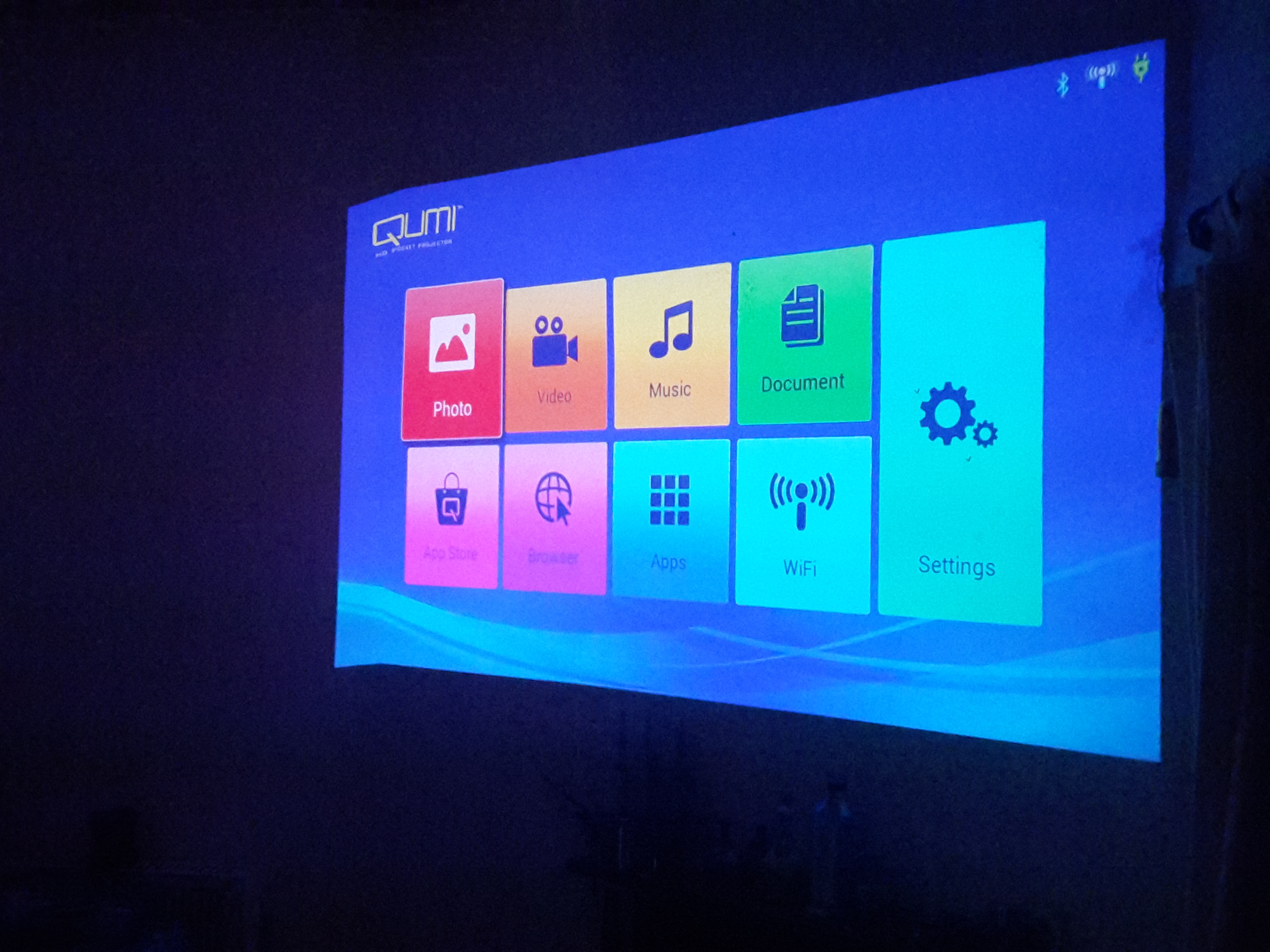
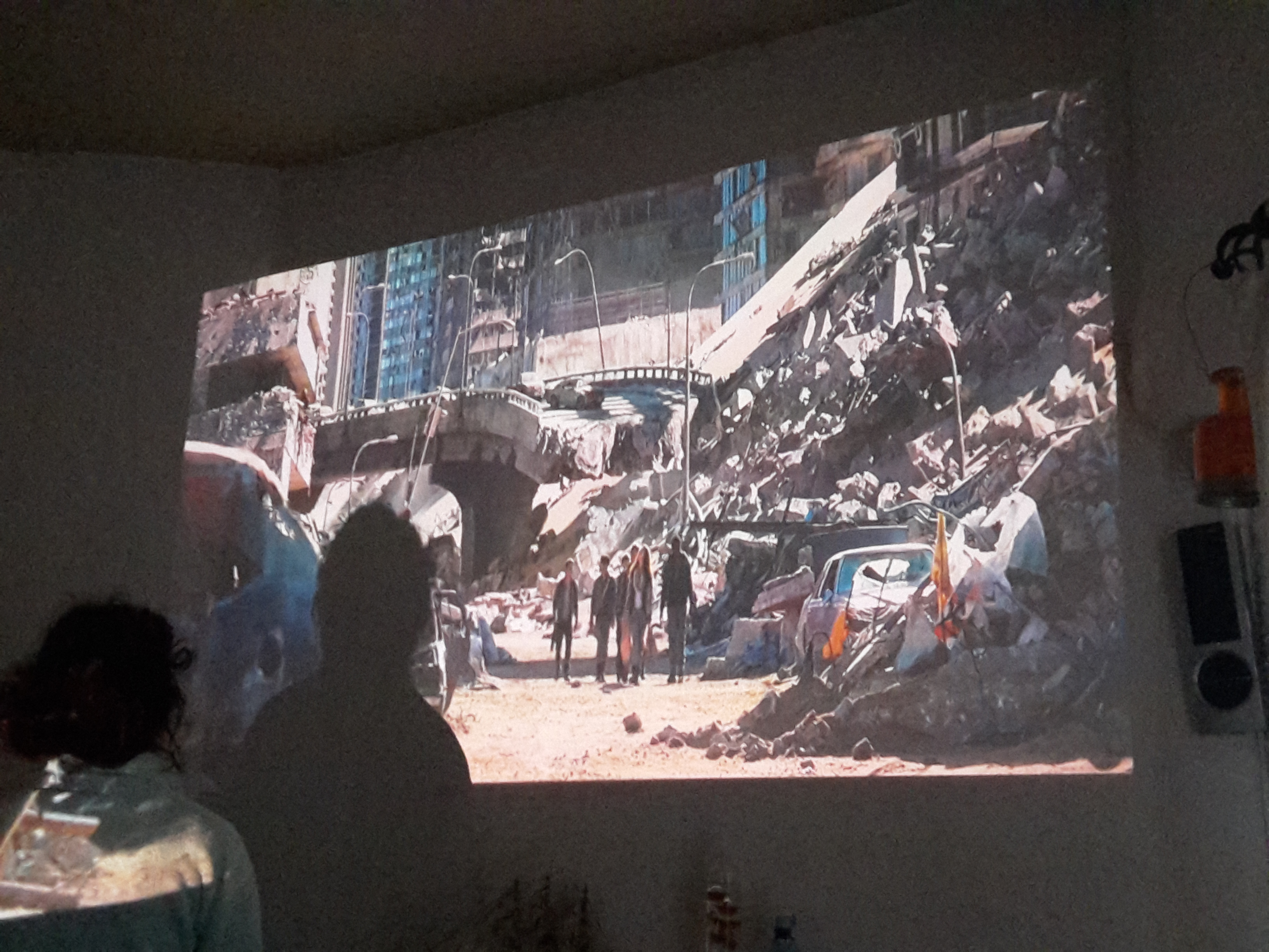
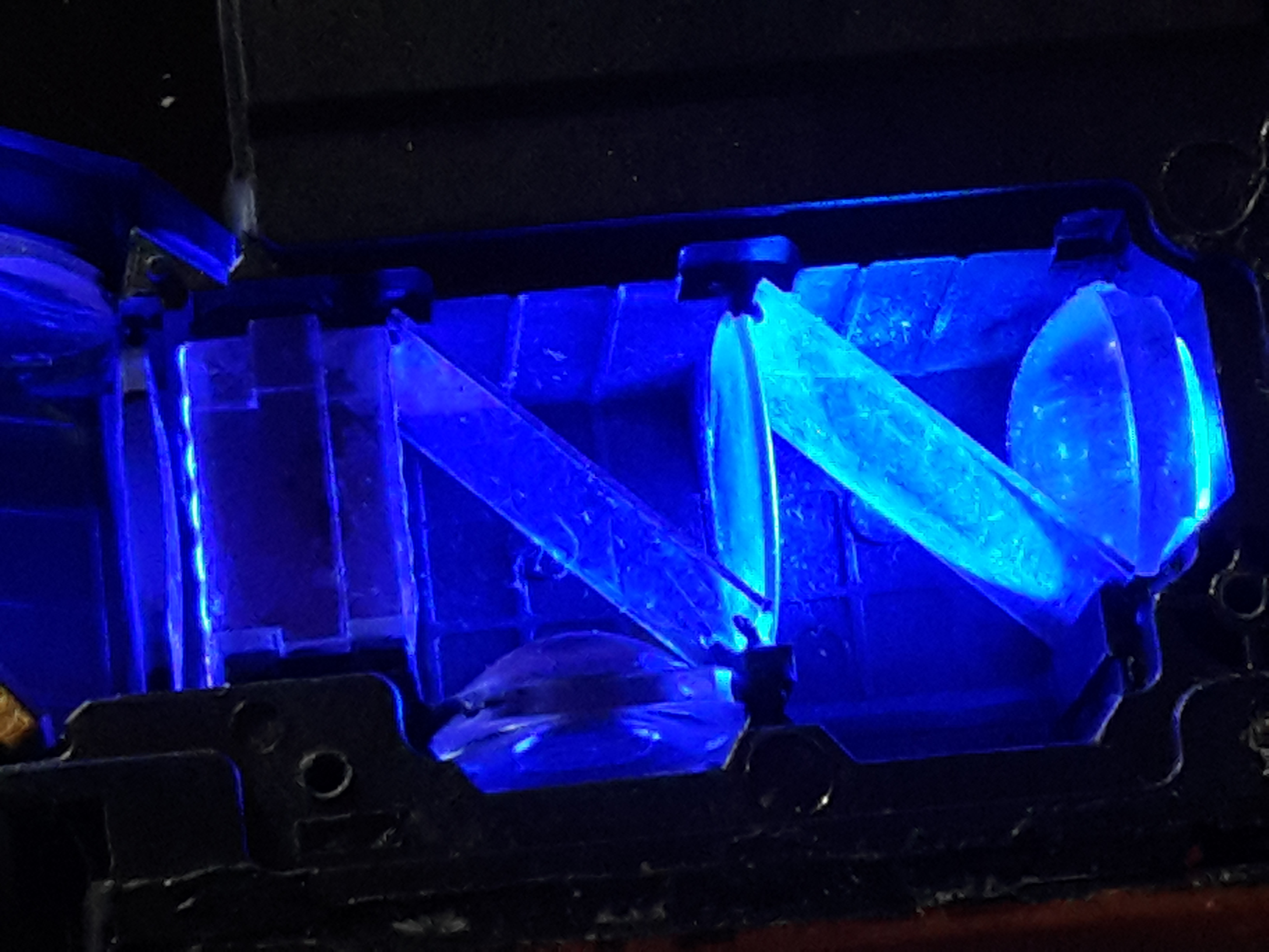
i have a projector, that i am aware contains a dlp light engine from yourselves, it has recently developed a problem where, it has dropped to about 25% light output after 800 hours of use, and the image has a pink cast, i am unable to see a part number, so i wonder if i give you the projector model you can find which dlp unit was used in this device..thankyou

manufacturer...vivitek

model..qumi q3 plus

manufacture date.. march 2017

  • Hi Michael,

    TI does not have information of the models that our partners use our products in. Please contact the concerned manufacturer directly to identify the part number.

    Regards
    Azad
  •  hi

    i have removed the dmd driver board from said optical engine (please see attached pic) it seems the optical engine is made by ongine, the symptoms are about a more than 50% drop in light output, with a pink/purple hue to the entire image, i am trying to figure out if this is due to a failed led or the driver board, from what i can see the green led is an osram ostar q8 led, which from the data sheet i have found should be emitting at 520nm but the light i see from the led is not green and more between 550 and 600nm, also this led is running hotter than the other blue and red leds, before this fault occured, the projector would be slightly dimmer at start up and have the slight pink/hue as said but after about 30mins operation it would be at full brightness with no color hue, i would expect a failing led chip to go worse as the unit warms up not improve

    can you confirm if it is yourselves who produced the dmd driver board in the pic or if it is ongine i need to speak to, and do you have any idea regarding this fault, would it be due to a failed driver board or more likely the led chip

    the driver board contains led driver chip 'DLPA30000'

    and dlp chip 'DLPC3438'

    with a 'DLPS051' dmd chip

  • Hi Michael,

    Thanks for identifying the chipset. However, this doesn't seem to be an issue with the DLP chipset, more likely a failed LED. Moreover, TI doesn't design or produce the driver board either, please contact the manufacturer directly for electrical issues with the board.

    Regards
    Azad
  • hi

    thanks for your reply, i have contacted the manufacturer to find out further info.

    i would like to access the chipset on the board via i2c in order to check led settings ect, i have a generic usb to i2c programmer board with chip CH341A, i have installed the drivers for the pc, and i have installed the evm gui tool, but if i check in the prefrences it only has listed for connections the devices cypress and devasys, it does not recognize my device is connected to the pc, is this software able to utilize other usb i2c devices and if so how am i able to enable it in the software, i am running win xp 64bit, i have also copied the usb i2c drivers to the ti gui tool folder, but as said it is not showing in the list as connected devices

    thanks for your help

  • Hi Michael,

    The EVM GUI only works with Devasys or Cypress devices as it only intended to be used with the EVM. In case you want to access the DLPC3438 controller through I2C, you should be able to use any generic I2C GUI that works with your usb to i2c programmer board and get the raw I2C values, assuming the usb to i2c bridge is the master of the bus. If the bridge is not able to take control of the bus, then you will not be able to communicate with the controller.

    Regards
    Azad
  • hi

    thanks for the fast reply, ok it is as i suspected

    do you have any reference docs regarding which addresses on the chip corespond to which commands

    also what cypress chipset is required by the gui in order to work


    thanks again

  • Hi Michael,

    Please refer to the DLPC3438 Software Programmer's Guide for more information on the I2C commands. It is available here: www.ti.com/.../dlpu020c.pdf

    The Cypress chip used in the EVM is CY7C65215-32LTXI.

    Regards
    Azad
  • hi

    thanks very much for the help regarding this, with regards to the led driver chip dlpa3000, if a fault with either of the leds is detected will it shutdown the optical engine or lower the current output significantly to all three r g and b led modules?

    also i understand that you do not create the optical engine, but as im still awaiting a response from the manufacturer, i would like to check a theory with you, please see below....

    when the optical engine starts up, for a few seconds before the system has fully booted up and projection begins, the lens used to omit a faint white light, i assume this is due to all three leds being powered up but the graphics processor has not yet begun processing image signals, and so what shows is the color mix from the rgb leds being mixed within the optical unit, now when the unit is powered up what used to be white light as mentioned above is now red/pink. surely if at this point all three leds are powered while the sytem continues to boot i should see white light more or less, i can see that all leds are lit from the light bleeding out where they connect to the optical system so why if red green and blue are being powered am i not seeing the mix (aka white) light in the output lense, it seems to me as if the green portion of the light is not coming through, and it is not related to the dmd board, do you have any ideas or have you experienced this similar fault, its almost as a if the dichroic mirror for the green has failed but it seems unlikely

    thanks for your help, and i understand the chipset is you domain and not really the optics, but as said im not having much response from the manufacturer
  • Michael,

    The DLPA3000 will not be able to detect a fault with the LED, it will still try to drive the same amount of current which would be driven under normal circumstances. This can result in unexpected outputs, and may also damage the LED driver itself.

    Regarding the reddish light output during startup, it does seem like an issue with the optics. Are you sure that all three LEDs are emitting light at the same intensities as before? Maybe the green (or blue) LED has dimmed to such an extent that it is no longer visible in the output.

    Regards
    Azad
  • thanks for the reply

    unfortunatley due to the design of the optical engine i am unable to access the leds to view the output intensity while they are connected to the dmd board, all i can go by is the light that bleeds out slightly from the mounting, i have however removed and powered each led chip independently and the light output is extreme,

    i think the thing is to remove the dmd board, and link each led so i can power all three leds together while attached to the optical engine..doing this i would expect to see white light emitted from the projector lens, which would rule out the optics and point more to the dmd board, if i still get a pink light then i can only assume it is an optics problem or maybe the green led wavelength has changed to such a point its not reflected by the dichroic?

    any ideas

    thanks again
  • Michael,

    If you remove the DMD, I'm not sure if any light would reach the projector lens as the DMD acts a mirror in the optical path from the LED to the lens. You could probably try replacing it with a mirror, though I'm not sure if it'd work optically as expected. Also, removing the DMD connection would prevent the system from powering up, so you would have to keep it connected electrically.

    Also, the LED driver wouldn't be able to power all three LEDs in series, so you could end up damaging one or more components. The DLPA3000 can drive enough current to power one LED at a time only.

    Regards
    Azad
  • hi thanks for the reply

    sorry i think you misunderstood me, i mean i will remove the driver board in the pic earlier in this topic, that contains the chipsets, leave the optical module with dmd chip intact, and use a bench power supply to power the three leds in parallel

    thankyou
  • hi

    problem discovered,

    the collimator lens for the green led has melted on the inside, this explains how i felt the green led running hotter than the other two, question is how has this happened, could it have been due to contanimants on the lens absorbing heat or something else, anyway it has not damaged anything else i will see if i can source a lens

    i will attach a pic as soon as i can

    thanks for the help
  • Hi Michael,

    Thanks for sharing this information. Good to know that you were able to identify the root cause. Please keep us updated on any further developments.

    Regards
    Azad
  • hi

    picture attached as promised, as you can see the collimator lens for the green led is completley burnt up, and has deposited particles on the dichroic mirrors, also you can see the lens for the blue led at the top has crazing on it, and on inspection a dark spot..so clearly this was going the same way too, i dont know if there was crazing on these lens from manufacture or there is uv light that causes this?(any ideas) at the bottom the lens for the red led is perfect


    i have managed to clean the dichroics(the best i can) now i just need to source new lenses, i have had no luck from the manufacturer regarding giving me info on these, if anyone has any ideas as to what the focal length may be for these that would be great

    lenses are 9mm dia, 2.5mm thick, edge thickness 1mm.

    thanks for all the help in the past with this
  • Azad said:
    Hi Michael,

    Thanks for sharing this information. Good to know that you were able to identify the root cause. Please keep us updated on any further developments.

    Regards
    Azad

  • hi

    above is the blue lens i have removed, as mentioned it was the lens for the green led that had melted, but as you can see this lens has also started, i assume due to the abrasions on the surface causing it to absorb heat, i think the abrasions have been caused during manufacture...

    i now have some replacement lenses and am in the process of fitting them

    i will update you when im done
  • optics cleaned, the pic shows some dirt still on the centre lens between the mirrors, ive cleaned since taking this pic, thankfully the mirrors were not damaged by the burning lens
  • Final pics, unit has been put back together, fitted two new collimator lenses, had to shape slightly at the edges in order to fit into the mounting slots within the optical engine,

    above are the test pics, approx a 100" screen, in a darkened room with some daylight coming through blinds. person stood there to give size comparison, overall brightness is good, color is good, and no artifacts are showing on the image, unfortunatly i did not take a picture of the image when the unit was faulty, but as said, it was easily less than 25% of the brightness you see in the picture, as well as having a pink/purple hue over the image

    overall pleased with the results

    thanks for your input, in the questions i asked, deep down i suspected the optics if i think about it

  • Hi Michael,

    Glad to know that you were able to get it working.

    Where did you source the lenses from?

    Regards
    Azad
  • Hi Azad

    i sourced the lens from amazon, the details are below as described on the page

    description:
    Outer diameter: 10MM
    Height: 4.5MM Step height: 1.5MM
    Light transmission rate: 93%
    Focal length: 7MM Beam angle: the angle can be adjusted
    Material: imported PMMA

    the only difference is they are fully convex lenses, not aspherical like the original ones, but as far as i can see the focal point is nearly identical to the original when i checked, and all light seems to be hitting the mirror fine.

    i have some pics i took when testing the blue led with the new lens fitted and the optical unit open to see where the light was collimating, i will attach these pics soon as i get them on the pc

  • pic showing the new lens for the blue led fitted in the top right hand corner befoe tacking in place with glue, the mirror was cleaned better since this photo was taken as there are quite a few smudges on there,

    if you look at the edges of the lens in the pic, you can see i had to cut slots away in order to fit the lens, though these lenses are the exact diameter of the old, the lens for the blue led would have contacted the dichroic mirror on the bottom edge (as seen in pic orientation) if i had not cut it away in order to recess it slightly, this was caused by it not being aspherical in shape, if it had of been it would have not contacted the mirror,

    lens for green led fitted fine (not shown in this pic), only put a slight edge on the side of the lens in order to slot within the cut outs for the lenses in the optical unit , removed .5mm of depth on either side of the lens