This thread has been locked.

If you have a related question, please click the "Ask a related question" button in the top right corner. The newly created question will be automatically linked to this question.

Compiler/DLPC350: Definition of Pattern Display LUT data command in firmware

Part Number: DLPC350

Tool/software: TI C/C++ Compiler

Hi,

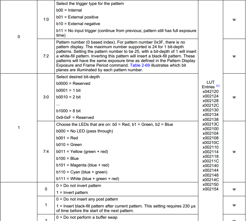
I am trying to understand the commands in the .ini file of the firmware. There is a command line  "DEFAULT.SEQPATLUT" in Default.ini file in Firmware that I cannot understand. I have read the corresponding table in the programming document, however, I still did not catch it well .

Could you please explain, for instance, what the command 0x00061800 means according to the Table?

I understood that 00 byte is the Internal Trigger.

  • Hello Semicolon,

    Could you clarify what part of the command you would like clarified? I would also recommend playing with the GUI (if you haven't already) and observe what commands are being sent. This definitely helps in understanding the sent commands.

    Thanks,
    Kyle
  • Hello user,

    Variables such as SEQPATLUT are generated by the LightCrafter GUI. Are you trying to manually edit these values, or are you trying to understand what the individual bits are doing within a configuration?

    Regards,
    Philippe Dollo
  • Hi Philippe, Hi Kyle, Thanks for the reply! I’m actually trying to edit them manually. I want to minimize the GUI code in C++ just to have sequence patterns. I want to send the information about the index, bit depth and so on by modify the buffer in firmware. Thanks in advance
  • Hi Semicolon,

    Before interpreting this parameter
    DEFAULT.SEQPATLUT 0x00061800 0x00022804 0x00024808 ;

    You also need to refer to
    DEFAULT.PATTERNCONFIG.TRIG_MODE 0x01 ; <1>

    The above parameter directly maps to I2C command (0x70); as mentioned above it maps to
    1 = Pattern Trigger Mode 1: Internally or externally (through TRIG_IN_1 and TRIG_IN_2) generated trigger

    Now back to DEFAULT.SEQPATLUT ; because TRIG MODE = 0x01; the pattern sequence LUT maps to command Pattern Display LUT Data (0x78)
    Table 2-69 Pattern Display LUT Data:Pattern Definition Command; as per the definition it is 3 byte data MSB byte is ignored and the order is MSB to LSB.

    As shown in above it has information for 3 LUTs - 0x00061800 0x00022804 0x00024808
    First LUT - 0x00061800
    BYTE0 - 0x00
    BYTE1 - 0x18
    BYTE2 - 0x06
    BYTE3 - 0x00 (Reserved don't care)

    Regards,
    Sanjeev
  • Hi Sanjeev,

    Thank you for your informative reply. I still have doubts about the numbers for each bytes, for example what does 0x18 (or 0x06) come from? I mean the number 18 and 6.

    Thank you so much for helping me out.

    Best,

    Semicolon

  • Hi Semicolon,

    For exact meaning for 0x18 (0r 0x06) BYTE1 and BYTE2 you can refer to controller software programmer's guide.

    In the http://www.ti.com/lit/ug/dlpu010g/dlpu010g.pdf towards end there are examples provided on how the table LUT is setup, refer to Table 4-1.

    Or

    You can simply use the GUI tool and create pattern sequence as you need then you can save it as new configuration .INI file and use it in the flash. In this case you don't need worry about creating LUT data.

    Let us know if it helps.

    Regards,
    Sanjeev