This thread has been locked.

If you have a related question, please click the "Ask a related question" button in the top right corner. The newly created question will be automatically linked to this question.

TPS63020 Regulator Issue

Other Parts Discussed in Thread: TPS63020


Hello TI,

               Below is the issue one of our customer is facing in boost mode. they are not achieving the Maximum current at load(using SOM module)

In transient (observed 650 to 700mV dip during boot up)

Input supply: 3.3V @ 4A                  

application requirement is below

 Output : Min 2.5A @ 3.3V for input ranging 3V to 4.1V.

 Input Source: Single cell Li battery capable of sourcing max 5A


Customer Query:

.       With the input of 3V @ 4A we were able to achieve 3.3V @800mA.


As per the datasheet expected current at 3V input is more than 2A @3.3V but we were able to get only 800mA. 

Customer requirement is min of 2A output at 3V input and were are able to achieve only 800mA?


Kinldyk

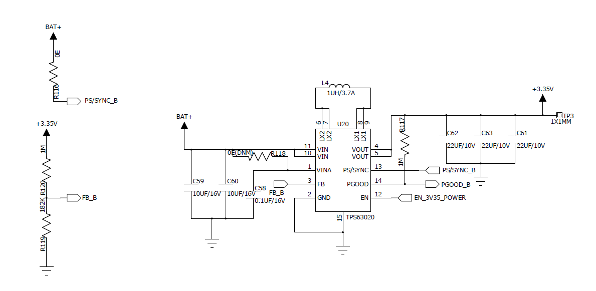
Kindly review the schematic which I have shared and suggest us for further proceed

Regards

Yashwitha


  • Hi Yashwitha,

    The device should be capable of delivering more than 2 A at Vin=3 V. The schematic looks fine, assuming R118 is not mounted. Could you please:
    1. Provide the PCB layout,
    2. Scope plots during startup and normal operation at Iout=800 mA: Vin, Vout, Iin, Iout, VL1, VL2.

    Please also make sure that there is a low-impedance connection between the battery (or the input power supply) and the VIN pin of the TPS63020.

    Best regards,
    Milos

  • Hi Yashwitha,
    Is there any update or anything I can do further to help to resolve the issue?
    Please post again or open a new thread if this one gets locked.
    Regards,
    Julian