This thread has been locked.

If you have a related question, please click the "Ask a related question" button in the top right corner. The newly created question will be automatically linked to this question.

DLP3000: External Pattern Camera Triggering

Part Number: DLP3000

Hey everyone,

I am trying to feed an external pattern into my DLP3000 board and have it trigger the camera trigger on each bit plane.

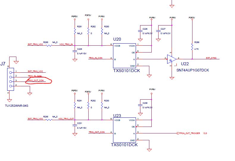
I have done the hardware modifications (adding 0 ohm resistor to R295). In the windows GUI I can get the camera trigger working with HDMI and I see the signal when I probe the correct pins.

However, for my application I want to use the C API. Currently, my code is roughly doing this:


if(LCR_CMD_Open()) { printf("Unable to connect to the DLP LCr\n"); } printf("Displaying HDMI"); LCR_CMD_SetDisplayMode((LCR_DisplayMode_t)(0x02)); // Set trigger output settings LCR_CamTriggerSetting_t triggerSettings; triggerSettings.Enable = 1; triggerSettings.Source = 0; triggerSettings.Polarity = TRIGGER_EDGE_POS; triggerSettings.Delay = 0; triggerSettings.PulseWidth = 200; //us LCR_CMD_SetCamTriggerSetting(&triggerSettings); //Get trigger setttings LCR_CamTriggerSetting_t triggerSettings; LCR_CMD_GetCamTriggerSetting(&triggerSettings); printf("Enable %u \n",triggerSettings.Enable); printf("Source %u \n",triggerSettings.Source); printf("Delay %u \n",triggerSettings.Delay); printf("Polarity %u \n",triggerSettings.Polarity); printf("PulseWidth %u \n",triggerSettings.PulseWidth)


This return:

Displaying HDMI

Enable 1
Source 0
Delay 0
Polarity 0
PulseWidth 200

If I probe the correct pin I can't see the camera trigger.

I was hoping someone could give me advice on what to do.

  • Hello Alexander,

    Just to confirm, you have the exact same video source setup and hardware setup between the GUI control and SDK control? And it behaves as expected with the GUI?

    Thanks,
    Kyle
  • Hi Alexander,

    Have you probed the hardware that you see trigger o/p pulses. If not first use GUI ensure that the trigger o/p pulses coming.

    Once you ensure it works then there is additional things you may want to consider for the camera working, most of the camera are opto-couples and requires different voltage settings so refer to this application note http://www.ti.com/lit/wp/dlpa032/dlpa032.pdf ; after reading through the application note, you may want to make the additional changes to get the camera trigger working. 

    Hope this helps.

    Regards,
    Sanjeev

  • Hi Sanjeev and Kyle,

    Kyle, I have the same hardware setup for both the GUI control of the camera trigger and the API/SDK control of the camera trigger.

    Sanjeev, I am not actually planning to use this to trigger a camera, I plan to route the signal to an external microcontroller for performing other processing. I can handle scaling the voltage etc for interfacing with other devices. I am currently just probing between ground and trigger-out with an oscilloscope.

    If either of you have gotten the camera trigger to work with external streaming over the API/SDK I would love to hear.

    -Alex

  • Alex,

    Just to make sure we understand your setup -

    You mentioned about external streaming , so i presume the pixel data is sent over mini-HDMI connector, is it the case?

    Now in external streaming mode, to get the syncs out on J7 Pin3 - make sure you are configuring the LightCrafter EVM properly? Use GUI to experiment first, enable trigger out,

    http://www.ti.com/lit/ug/dlpu004b/dlpu004b.pdf 

    Section 2.3.1.1.2.4 8-bit Monochrome External Video onward you will see various configurations, in streaming, once trigger out is enabled, you must see the signal depending upon the selected bit-depth.

    If you are not seeing then there is some-other hardware issue we need to look at, since you mentioned about probing, did you look on o-scope?

    The other option is to install R295 and then select voltage via R281 or R282 or R283 resistors then you can use J7 Pin 1 also to interface with the microcontroller.

    Regards,
    Sanjeev